Eng-Tips is the largest engineering community on the Internet

Intelligent Work Forums for Engineering Professionals

Miami Pedestrian Bridge, Part I 65

Status
Not open for further replies.

JohnRBaker

Mechanical
Jun 1, 2006
35,343
2
38
US
Multiple Fatalities After Pedestrian Bridge Collapses Near Florida International University


As investigators continue to search the site of a deadly collapse involving a 950-ton pedestrian bridge near Florida International University in Miami Thursday, officials say the death toll has risen.

Early Friday morning, the Miami-Dade Police Department confirmed that six people have died as a result of the collapse....

John R. Baker, P.E. (ret)
EX-Product 'Evangelist'
Irvine, CA
Siemens PLM:
UG/NX Museum:

The secret of life is not finding someone to live with
It's finding someone you can't live without
 
Replies continue below

Recommended for you

output_jdjfnF_ckjo6r.gif
 
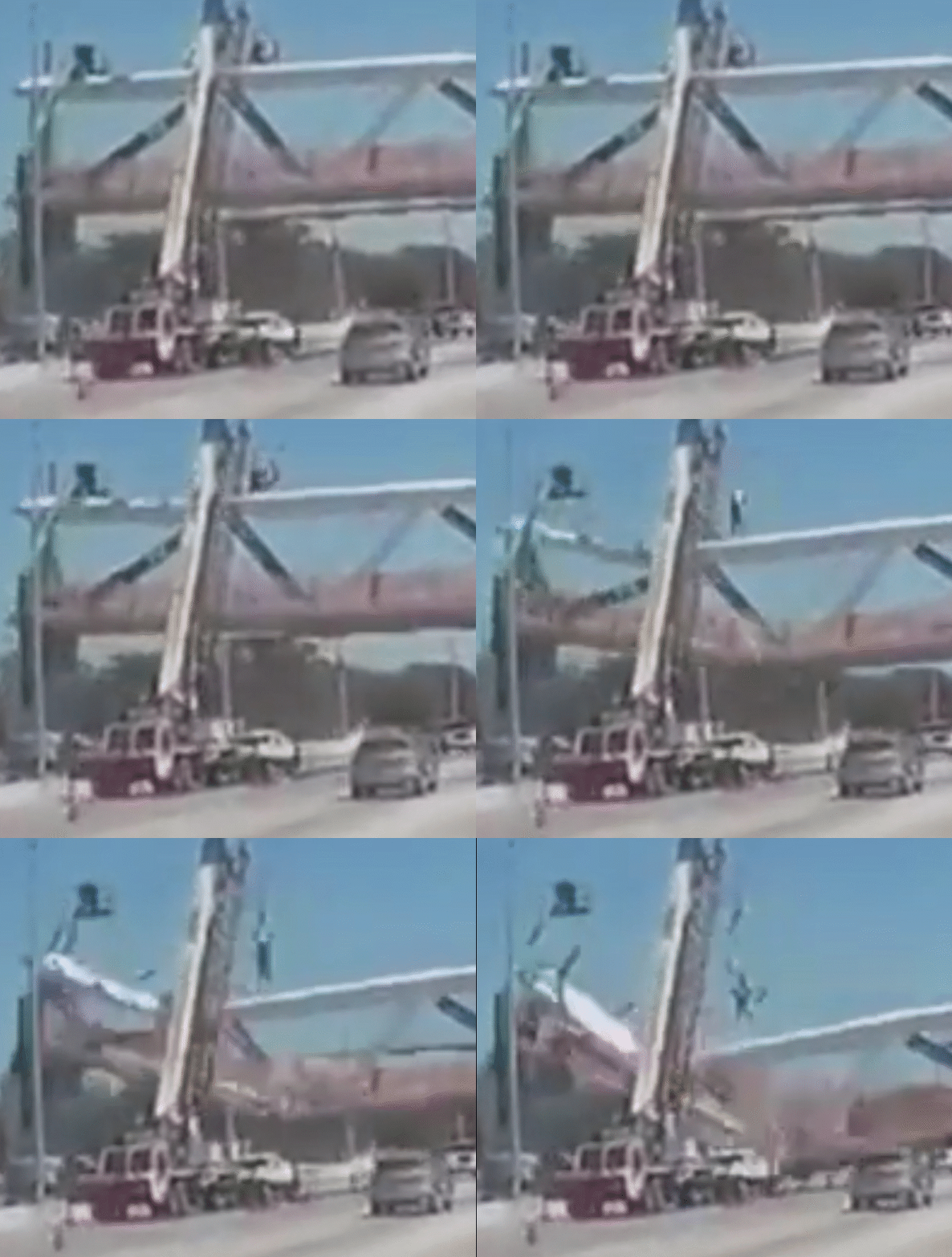
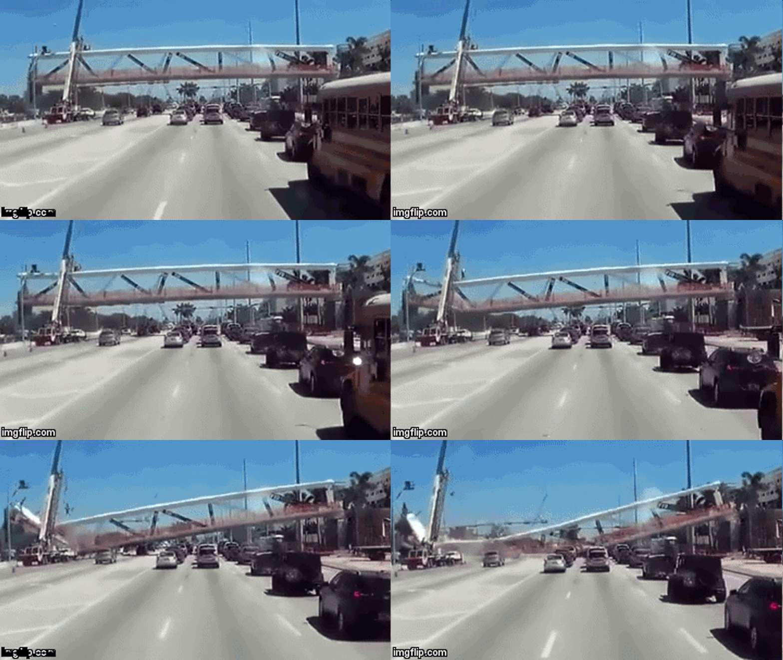
I made a gif of 11 frames and cleaned it up a bit. Let's see if it loads.
FIU_Bridge_lgdnan.gif
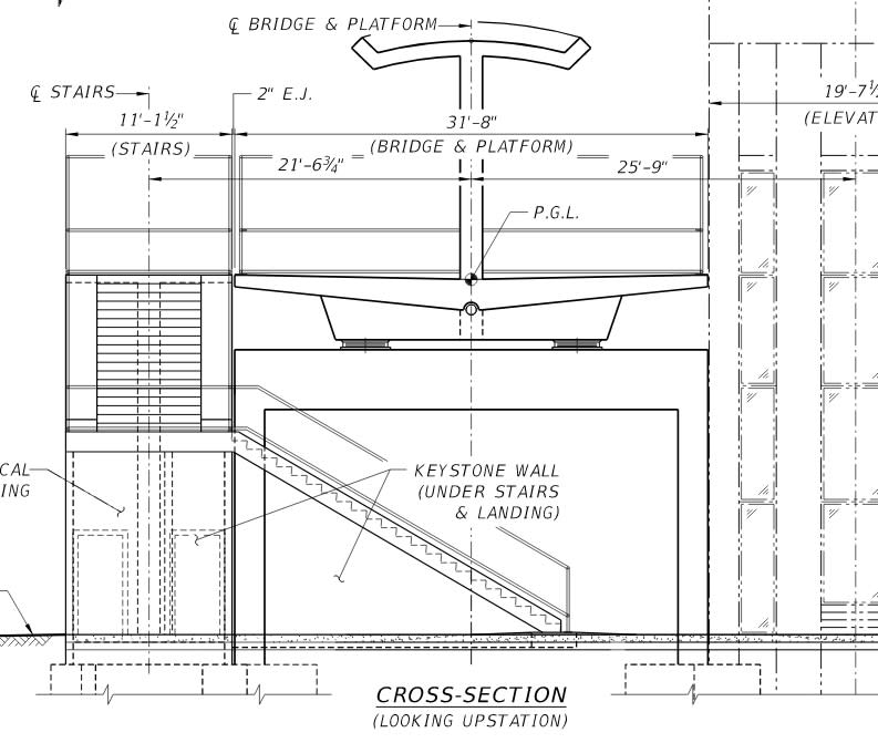
Well okay & the 10MB is in the attachments. I cleaned it up as best I can. After looking at the failure to the top left of #11 and to the bottom left of 10 & 9, I wonder if the position of the drains & the recess under the bridge for the drain pipe didn't create a point of weakness. Link

Bridge_Cross-Section_sjgl5a.jpg
 
Tomfh...great video w the dash cam...i see an explosion at the bottom of the vertical at the support...maybe the strand they were pulling at the top of #11 came out at the bearing node of the truss...the tension diagonal adjacent to #11 appears to punch thru at the bottom as well
 
Tomfh your cleaned up video is great! You should give copy to each party concerned. It looks like tensioning of the truss going down t the left pulled the top and the adjacent truss going down to the right and thus breaking the walkway then the top chord also broke.
 
Thank you all for providing all thoughts and supporting documentation for this horrible accident. It is very obvious that de-stressing or stressing the tendon in #11 triggered the collapse. This diagonal should be completely de-stressed when the span was placed on the piers, but apparently it didn't happen. The cracking reported prior to the accident should result in emergency shoring of the bridge, as any crack in post tensioned structure should trigger such action.
The design of this pedestrian bridge was apparently driven by the appearance, not the structural efficiency and safety. The truss could serve without stays, but single diagonals and posts were not sufficient for the wind loads and required redundancy.
As usual, the devil is in the details - lack of mild reinforcement at the joints, where the stresses are almost unpredictable, post-tensioning of the compression member lead to this disaster.
Eugene Figg was a great engineer - but apparently the "successors" do not have the same capabilities. And even greatest legacy do not do the design - it's just the designer in charge of the project.
So, the recipe for for disaster is rather simple - great legacy company, inept design, and no response to apparent overstress signs.
Just bunch of idiots running the project.
 
Excellent and sobering discussion. It seems pretty likely that de-stressing member 11 caused the collapse. If the temporary PT was stressed to 200 kips, de-stressing it would have significantly increased the tension in the adjacent members. Listening to the voicemail was really chilling. I am certain that I have spoken almost the same words more than once in response to s**t happening during construction. Very often, the cracks we see really aren't safety issues. Engineers are human and can make mistakes. What kind of systematic rules could prevent this from happening again? Definitely no adjusting PT in non-redundant structures with traffic below. But in general how do we make sure the right decisions are made, especially during design/build projects?
 
graybeach said:
What kind of systematic rules could prevent this from happening again? Definitely no adjusting PT in non-redundant structures with traffic below
How about not designing non-redundant structures...
 
We'll wait and see what the 'official' cause of the collapse was; hopefully it will be similar to this thread. It would be great to have copies of photographs taken of the 'crack', just to see how insignificant it was. The EoR was likely doing 'damage control' in the event others brought up the crack.

It will be interesting to see if the project goes ahead, and, if there is any 'political spin'. It would be nice to see if the funding is challenged.

I was really surprised that the collapse was 'instantaneous', without warning, other than maybe the earlier crack. The EoR will likely carry his statement about the insignificance of it to his grave...

Dik
 
This photo indicates that the deck slab which was acting as the tension chord of the truss, pulled away from the column and pier. The end diagonal, column and canopy slab still seem to form a triangle after collapse, although the connection between the end diagonal and column cannot be seen.

BA
 
 http://files.engineering.com/getfile.aspx?folder=014275c1-8eb3-439a-aff1-4475400041c5&file=Screenshot_from_2018-03-18_07-08-17_3C670378-DD85-8B02-7295E71FE4D9F62F.png
Reading through the above and (most of) the links, I can't see anything to say where the pre-failure cracks were found - apart from the "at the North end" in that voicemail message.

Have I missed something along the way, or do we not actually know that yet?

I wonder if the cracks might eventually turn out to have played no part in the ultimate failure. Too early to tell.

A.
 
BA, I had noticed the same thing... that the top chord, end vertical and first compression diagonal seem to still form a triangle after the collapse, but, as you point out, it's not clear what the condition or status of the joints is, or whether they are even still really connected or simply "leaning" on each other.
 
Also, in the screen shot that BA posted a couple of comments up thread, it looks like, in general, the PT anchor "blisters" on top of the canopy/top chord have mainly stayed in tact but fractured or sheared off the from the main canopy/top chord. That seems odd to me, unless they had been cast separately, had a higher f'c, had some mild steel reinforcing in them, or something along those lines. Anyone else think it is odd that the anchor "blisters" would stay in tact but separate from the top chord?
 
gte447f, true but there can be no doubt that the tension chord became disconnected at the end; and without the tension chord, the truss must fail.

BA
 
Wikipedia provides some details (with links to sources).

"An eyewitness reported that at the moment before collapse, a blue box fell loose from a crane hook, dropping onto the roof of the bridge very near where the roof and span then immediately broke apart."


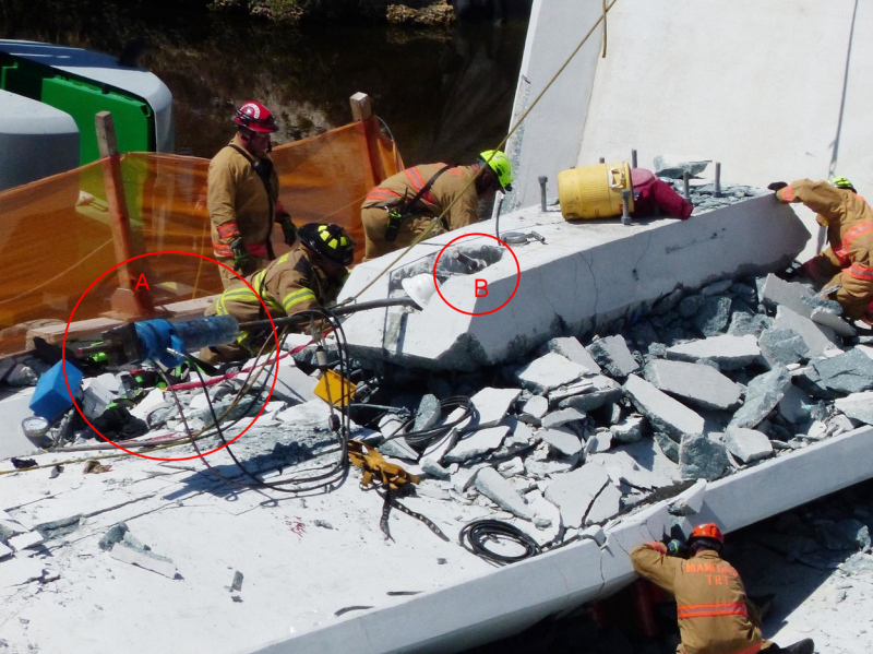
BA, yes, definitely can't have a truss without a tension chord. Look at the zoomed in video posted by Tomfh up thread a little bit. It is very fuzzy, but in the second frame, it looks like you can make out something shooting up vertically from the top chord first panel point and in the same frame there appears to be an "explosion" of dust at opposite end of diagonal #11 at the bottom chord bearing end bearing. What we see in this frame could be the result of the PT rod rupturing under tension and erupting out both the top and bottom ends of diagonal #11. The object that appears to shoot up in the air from the top chord would be the stressing ram still attached to the live end of the PT rod. The dust cloud at the bottom of the diagonal would be the dead end anchor plate erupting out of the concrete. What do you think?
 
From this reddit post someone spotted two tendons in the PT Blister and if the mysterious "Blue Box" was the the control box in the same picture and it dropped, well..., that would have been very bad. Link

bLTBa6e_v9tqyr.png
 
I'm skeptical of the "reports" of a blue box being dropped from the crane onto the canopy/top chord just prior to the collapse. Some of the same reports mention the blue box hanging from a blue cable. Who has ever seen a blue cable? Some of the same reports that mention the blue box falling from a blue cable quote congressmen as saying things like, and I am paraphrasing here, "they were conducting a stress test... they were impacting the bridge with a load to see what it could handle", implying they were intentionally dropping a load onto the deck to see if it could handle the impact. Of course that is absurd. Even Marco Rubio has made statements about the "cables that suspend the Miami bridge", when of course we know there are no suspension cables involved. So, there is a lot of uninformed information out there.

Now there was a crane there, and you do wonder why. What was its roll during the tensioning/detensioning operation that was going on? Could something have fallen from the crane? I suppose so, but why would something fall from the crane, and what would be large enough to contribute to the bridge collapse? What are the chances of 2 catastrophic failures (the crane and the bridge) happening at the same time, or I suppose one catastrophic failure resulting an an immediate second catastrophic failure?

Of the two blue things in the photos of the collapsed bridge, one (the cylinder) is the stressing ram/jack and is still attached to the PT rod which has clearly erupted from the diagonal about 5 or 6 feet, and the other (the box) I think is the hydraulic gage to monitor the jacking force. I think this gage would have been on the deck right next to the workers stressing the pt rod, not suspended from a crane.
 
Thinking out loud, all of the stressing equipment (hydraulic ram/gauge/pump) is heavy to lug around, and likely would have been hoisted up top with the crane instead of manhandling it up there. You can see maybe a lifting line and a red tether in the photo above that may still be attached to some of the equipment (I can't tell). Or, could it have been fall protection for the workers?
 
Status
Not open for further replies.
Back
Top