Eng-Tips is the largest engineering community on the Internet

Intelligent Work Forums for Engineering Professionals

Miami Pedestrian Bridge, Part V 71

Status
Not open for further replies.

dik

Structural
Apr 13, 2001
25,564
0
36
CA
This continues the discussion from Part I, II, III, and IV. Please read the other threads first:

Part I
thread815-436595
Part II
thread815-436699
Part III
thread815-436802
Part IV
thread815-436924
 
Replies continue below

Recommended for you

There are a few posts about the rods which I think are answered elsewhere, but the amount the rods stretch to achieve the required tension in members 2 and 11 is an order of magnitude more than the concrete member itself would compress further once the beam was loaded onto the pier. Thus while the tension in the rods would have reduced a little, they would still be under considerable tension.

It was very tempting early on to see the tensioning gun and the tendon snapping as the "smoking gun", but a lot of people now don't think this is credible.
1) the crew were an experienced crew
2) you would need to pull it a considerable amount before it got to UTS
3) the rod should have been seeing less tension than it did when it was installed
4) the Collapse and separation of the deck and tendon from member 11 means it ended up in a shorter distance under the deck and hence stuck out the top end.


Remember - More details = better answers
Also: If you get a response it's polite to respond to it.
 
Quote SheerForceEng
"Do we know when the PT cables in the bottom deck/chord were stressed? Were these cables stressed after the entire truss was poured or was the bottom deck poured, then stressed, then the diagonal/verticals poured and so on?

If the cables in the bottom deck were stressed after the vertical and diagonal members and top chord were poured, this would put significant added stress to both the tension from the bottom deck trying to find its way into the node joining members 11+12 (thus magnifying the pull out failure eluded to earlier) and it would also result in some of the PT force finding its way up into member 11 as well thus further increasing the compressive demand on this member itself."

Discussed the pour and order of prestressing back in Part III at 18:00:03. Just to reiterate the structure was to be completely poured. It appears that the cold joints in the web are near the top and bottom flanges. The bottom flange was to be stressed first, if done all at once this has a significant impact on the diagonals in the web if stressing done in one step. Same between the web and canopy. Not sure if this is how it was actually done but it is most probable from their original intentions. Not sure when deck strands and canopy strands were grouted.

Obviously the prestressing if done in one step puts significant stress into the web members particularly 11 and 2 at each end. 2 appears to be beefed up compared to 11 which possibly saved it. I did horizontal and vertical shear calculations for 11 in part IV using 32.5 deg angle for 11 so these are slightly high compared to a 36 deg angle. Values are high enough to warrant a complete failure analysis of the concrete in this area due to all combined stresses. Does not appear to be enough deformed rebar to prevent failure.

There are so many ifs in this entire thing that any final conclusions are difficult. Until the NTSB releases more it only encourages more speculation.
 
Flicking through some of the past posts I wonder / hope that someone is searching the bottom of the canal. There seems to be a big chunk of the bottom of member 12 missing....

Remember - More details = better answers
Also: If you get a response it's polite to respond to it.
 
Is the 950 Tons reliable? PDF Page 107 of the MCM-Figg Proposal gives a lifting weight 915 tons for the 174.875 foot section. That can easily be misheard as 950 tons and go viral on TV. Using the 915 ton and adding 11 feet to the main span increases the length by 6.3%, yielding 972.5 tons. I don't see where there was room to shave 20+ tons off the original design+11 feet. By reference, page 108 gives the lifting weight of the Back Span as 565 tons (If Precast).

Member #3 suggests 10 bars in the standard size trusses Link

While not conclusive, it looks like the PT strands for #11 were routed left & right of #12 into the diaphragm.
Strand_b4ardo.jpg
 
One last question from this beginner ?

just thinking aloud because i'm not qualified to assert anything about concrete.
Happy to see questioning the sequence of tensioning.


Tensioning the deck and canopy separately i would think changes their relative lengths by elastic compression . That makes the right rectangle into a trapezoid with non=parallel ends. . How much difference is enough to put a hurt on member 12 at its bottom joint ?

Young's Modulus ?
wikipedis said:
The publication used by structural bridge engineers is the AASHTO Load and Resistance Factor Design Manual, or "LRFD." From the LRFD, section 5.4.2.4, Ec is determined by:

....... (omit a lot of text formatting characters that don't work here)....
E_c =1820 sqrt f'_c (ksi)
just say 5000 psi for f'_c = 5 , using ksi
E_c = 1820 sqrt(5 ) = 4070

So, a 175 foot span might change length by 175/4070 = 0.51 inch per 1000 psi of compression ?

I don't know how to figure the bending stress at bottom of #12 from a half inch deflection at its top.. MC/I ?
Intuitively seems not much. But it's the kind of question that nags at a beginner.
Would appreciate a dismissal by anybody skilled in the craft.

old jim


Never trust a computer with anything important...
 
The drawing that I have of the overall structure is stamped, dated 12/9/16 and signed by the Engineer. Not sure about US dating convention but it is either Dec. 9 of 2016 or Sept. 12 of 2016. The span is shown as 175' on this drawing; was the 11' added later than this. Here in Canada we would not stamp, sign, and date any drawing which was not clearly marked whether it is for tender, approval, review, not for construction etc. How does it work in the US. So is the final span 175' or 186'. I assumed 175' but now not positive.

Anyone?
 
If working was on upper PT bar instead lower one, probability of joint failure between member #11 and #12 as cause of collapse is significant higher.
snapshot03A_gjwzkf.jpg

Right now I'm really more confused by this picture.
 
chris snyder near the end of thread IV sketches a counteracting compression force from the first diagonal of the south span. I believe that is a misunderstanding. In a cable-stayed bridge the ends of the span would indeed thrust against one another at the central bearing. But this is not a cable-stayed bridge and the thrust must be countered by lower chord tension in both the temporary and final configuration. If the designers in fact assumed such a force it would have been an error.

Edit: sorry, I keep getting the compass directions reversed in my mind. I meant the to-be-constructed North span.
 
Video just posted on utube appears to shown bridge the morning of collapse
At 8:53 AM, westbound travel appears to show worker on south end canopy. No "apparent" north deck blemishes or cracks---video is fuzzy somewhat.
At 9:39 AM, eastbound travel shows crane setting up, maybe the man lift basket in roadway.
 
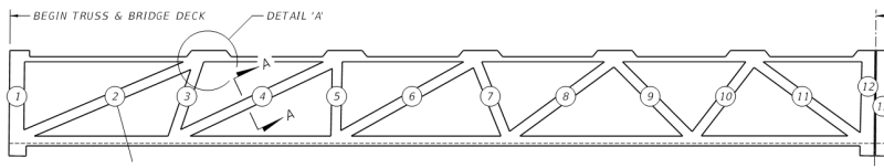
from the MCM/Figg proposal - differences between north No.11 and south No.2

(a) The end beam or downstand sitting on bearing : south side 3'-6" wide, north side 2'-10-1/2"
(b) First vertical member : South side No. 1 is 3'-0" wide, north 2'-10-5/8"
(c) Geometry of first diagonal Vertical:Horizontal:diagonal ratio : south side No. 2 has 1:2.14:2.37, North No. 11 has 1:1.4:1.7 approximately
(d) Axial compression of first diagonal : South No. 2 has 200kips, north side none specified.

My interpretation is a horizontal line drawn across No.2 and 11 then No. 2 has (2.37/1.7-1)*100 = 39% more horizontal shearing area than No. 11. However at a flatter slope but with the same support reaction the horizontal component or shearing force of No. 2 is (2.14/1.4-1)*100 = 53% higher than No. 11. The end result would be under identical reaction No. 2 should experience about 10% higher stress if a failure takes place on a horizontal plane.

However the axial compression is specified in No.2 and none for No.11 for the bridge being supported without free overhanging cantilever at either end during the move in the proposal drawings. So if No.11 subsequently were post-tensioned and then released/adjusted on completion then one can expect No. 2 to be similar but still has the specified 200kips left behind. When a member is compressed its shear resistance should increase. May be on balance the south side is more robust against shearing failure than the north side which collapse first.

Lastly some have raised the suspicion on the tension adjustment equipment and wonder if the members were further compressed. Two facts are relevant here:

NTSB news release 3/21/2018 said:
"The investigative team has confirmed that workers were adjusting tension on the two tensioning rods located in the diagonal member at the north end of the span when the bridge collapsed. They had done this same work earlier at the south end, moved to the north side, and had adjusted one rod. They were working on the second rod when the span failed and collapsed. The roadway was not closed while this work was being performed."

(1) The crew was adjusting tension. It can be increasing or decreasing tension. Since No.2 and 11 are permanently under compression in service one would have thought the original tension introduced to counterbalance the overhanging cantilever action would be removed in the tension adjustment. Any suggestion of the No.11 failed by compression could be speculation unless newer information is available.

(2) It would be speculative to blame the equipment or the workmen if the crew has adjusted successfully two PT rods on the south and one in the north.
 
Meerkat 007 said:
Right now I'm really more confused by this picture.

After primary failure at base of 11, I believe there was significant secondary grinding going at base of 11 prior to bridge collapse, with vertical 12 still in place. Other members begin to fail around it--first top canopy, then finally bottom slab. When bottom slab hinges and rotates prior to being pulled off of pier, this could force top PT rod out from top canopy. Then what's left of 11-12 are thrust off slab and onto top of pier as bridge plummets to ground. Of course, this is just a theory?

[[EDIT: Scratch the rotation of bottom slab thought, as it is the bottom PT rod, not the top as I mentioned above, that extends from the anchorage blister.]]
 
Meerkat 007,

I do not know what your last drawing depicts either.

However it is reasonably established the top PT rod of No. 11 has been adjusted successfully. The bridge broke when the crew was adjusting the tension in the bottom PT rod because the jack was still attached to the rod after the collapse.

Where we like it or not the tension adjustment of the last PT rod, at the bottom of No.11, triggered the collapse.

I was confused by the PT tendon and PT bar so to help others I stated the following:

The deck and canopy were post-tension by PT tendon or strands, each 0.6" diameter, which are flexible and can be bent.

The truss used PT rod or bar 1-3/4" diameter which has threads and difficult to bend. The tension adjustment should be tightening or loosening the nut at the exposed end. From my experience PT bar has a nut at the concealed end too. The rod, nut and the anchor plate there are often welded together and cast in concrete to provide a locked end.

 
Remember that the upper PT rod was adjusted at the lower end so the top end may be cast in the concrete.

The upper PT rod has stayed with memmber 11.
The lower end of the lower PT rod seems to be still attached to the deck.
This may indicate that the failure originated mostly above the deck.
Bearing in mind that the photos may be misleading.

Bill
--------------------
"Why not the best?"
Jimmy Carter
 
Old_jim said:
I don't know how to figure the bending stress at bottom of #12 from a half inch deflection at its top.

I wouldn't lose sleep on this one.

First the canopy is post-tensioned by 62 strands but walkway deck is also post-tensioned by 214 strands so stress on No.12 is difference of the two axial shortenings.

Secondly the canopy is mainly connect to No. 12 only by its 1'-0" thickness while the bottom of No.12 is cast with a 4'-0" deep beam. If the canopy is not strong enough to pull and bend No.12, due to insufficient bonding concrete for stress transfer, then the canopy edge will adjust itself by having less than your calculated shortening or developing cracks. I would say the middle section of canopy directly above the truss is not as compressible as the rest because the truss connections. May be that is the reason the designer move the 4 set of PT tensions away from the center.
 
meekat007,

The lump is the local thickening of concrete above each truss joint. It also serves as the tension adjustment point.

Capturemiami_wno3we.png


It is detail A but on top of member 10-11.

or are you talking about other bits?

A better view from the other side
protruding_PT_rod_gqlhij.png
 
Meerkat 007 said:
I'm confused by this

Not sure what you are pointing to inside that red annotation. Perhaps it's the white PT tube, and you're wondering if it's the lower PT tube of #11, which make the adjusting one the upper PT tube? (Except an upper #11 PT tube is visible in other photos.)

I the one you're looking at is more likely the most inboard of the canopy's PT tubes.
 
Status
Not open for further replies.
Back
Top