Eng-Tips is the largest engineering community on the Internet

Intelligent Work Forums for Engineering Professionals

Miami Pedestrian Bridge, Part V 71

Status
Not open for further replies.

dik

Structural
Apr 13, 2001
25,564
0
36
CA
This continues the discussion from Part I, II, III, and IV. Please read the other threads first:

Part I
thread815-436595
Part II
thread815-436699
Part III
thread815-436802
Part IV
thread815-436924
 
Replies continue below

Recommended for you

PE2015 said:
26 Mar 18 21:53 Video just posted on utube appears to shown bridge the morning of collapse
At 8:53 AM, westbound travel appears to show worker on south end canopy. No "apparent" north deck blemishes or cracks---video is fuzzy somewhat.
At 9:39 AM, eastbound travel shows crane setting up, maybe the man lift basket in roadway.
www.youtube.com/watch?v=CVjBiFMXjwU

Just want to draw attention to this earlier post. The linked video, shot from approximately the same angle as the dashcam collapse video, is quite useful in showing the various visual distractions around the north end of the bridge, including a tree in the background, and a lamppost in front.

One may also see how the north west corner of the deck visually protrudes "beyond the end of the bridge" as the car moves east. However, it's debatable whether it does so at the right rate to correspond to the similar visual appearance in the dashcam video.
 
This is only partially useful, but some may find it interesting. I took the elevation drawing from MCM FIGG Proposal of 2015-09-30, and mapped black to red, white to transparent, and used it here as an overlay on two of the most straight-on photos of the bridge I could find.

Here is the effect of fitting the drawing to the end verticals (#1 and #12):

elevX2_red_overlay_nkcr9o.png


And here is the effect of fitting the drawing as closely as possible to members 2 to 11.

elevX2_red_overlay_fit_members_mkuf96.png


In each case I scaled the drawing uniformly with 1:1 aspect ratio.

This exercise is not perfect by any means.

1. Obviously perspective. I have scaled the overlay uniformly and positioned it to match the end verticals (#1 and #12) or the other members (2 to 11), so this is an attempt to get the elevation drawing to match the centerline elevation slice of the bridge.

2. We don't know if the 175 ft length is before or after the additional lane was added. Others in the thread reported that both ends of the bridge moved north by 11 ft, others think that the bridge got longer, but we don't know if 175ft is before or after this. If the bridge is actually 186ft (say), and I matched the 175ft drawing to it, that's only about a 6% mismatch, and might not be noticed in mismatch of the deck and canopy, for example.

I have attached a transparent gif of the elevation overlay in case it's useful to anyone.

 
I was curious about the basic geometry, and how far would the lowest point of the deck have to fall in order for the north end to clear the edge of the pier.

Not all variables are known for this, for example exact length of bridge (I used 175 ft), and amount by which the north end of the bridge overlaps the pier (I used 3 ft).

gwfiu_deck_fall_geometry_bq1tru.png


So if there's a single fold, and it's at the base of #10 and #9, then when that point descends about 13ft, the north end of the deck is clear of the pier. Of course, it might clear earlier, if the folds are more complicated. And there's some chance the deck might initially stretch a little, or pull the pier inward.

I've also noted that when the deck is on the ground, if it stayed in two contiguous pieces it would impinge on the pier. As it turns out, the north end of the deck rests just short of the base of the pier, consistent with the deck shortening a bit corresponding to multiple folds at several locations.
 
Google Maps street view of section under construction on the side of the road. Can be zoomed and angle of view adjusted.


Youtube video everyone has seen, but now with overlay of members, frame-by-frame.


New youtuber video. I have no comment on it's veracity at this point. (Update: Not to be taken seriously, absurd assertions made.)

 
Let's go back to the bottom PT rod here.

Two massive assumptions here:
1) the crack that was being talked about was at the base of the no 11 member with the deck or somewhere close to it
2) to "pull" the crack back in line they decided that the thing to do was tension up the PT rods bars as the anchor point was beyond the crack and it would then close up or arrest the crack growth.

However in doing so they actually then increased the compressive stress and force on the bottom of member 11 which found its weak spot and just went bang?? Maybe if the bottom PT rod was not straight, but bent over to anchor into the slab it actually started to pull out of member 11?

It wouldn't have taken much movement of member 11 (a few inches?) before it effectively lost all compressive force and as far as the structure was concerned then became redundant, leading to failure of the remaining parts of the structure.

I do always wonder when things are built in stages / separately, whether enough design and analysis is undertaken on those stages and not just on the final item. It's fairly clear that the second span would butt up to the first span on the other side of the pier and then combine to make the tower structure. This would then help spread the load and prevent a blow out type event.

As an aside, every time I look at that bridge from the recent dashcam footage or the one where someone wanders around the bottom deck just after it went up, those members just look puny.

Remember - More details = better answers
Also: If you get a response it's polite to respond to it.
 
jrs87 said:
Philadelphia Construction Engineering video " I have no comment on it's veracity at this point. "

Yeah that guy keeps popping up in my search results too. Disorganized chaotic stream-of-consciousness blathering. He makes a few points that are not wrong, amongst a pile of misunderstandings about what has been reported, and jumps to conclusions with little insight into what is not known. At one point he claims maybe they put the entire bridge in backwards by mistake.
 
I find chris snyder's post with wusf news containing a recording by Tony Pipitone disturbing.

According to Tony Pipitone after the bridge had been lowered into its final position the stresses in the diagonal members were released and finished.

However as cracks were discovered two days prior the collapse a meeting was quickly convened between D&B consortium, Owner FIU and FDOT. After the meeting the Chief Engineer (presumably from the D&B consortium) ordered the crew to do extra stressing work. This implies the stresses inside members No.2 and 11 were "changed" possibly as a mitigating measure to cure the cracks.

The NTSB did carefully use the word "workers were adjusting tension" when they released the news but Tony Pipitone information suggests the action, which triggered the collapse, was a repeat of something already executed before. The action that caused the bridge to collapse is therefore not part of the original design, which would have been reviewed, approved and documented formally but a quick fix to cure or minimize the cracks in a hurry.

Sound like a Chernobyl accident to me.
 
chris synder,

Yes my response was partly amined at your previous post.

~Can you go back and look at / edit your post of 00:32 today? The pictures you have all of the upper tension rod in member 11. The lower one remained with the deck and was the one ripped out of the bottom side of member 11 that you can see in a lot of the previous photos. Your text keeps changing between upper rod and bottom rod.

I haven't seen the end point of the bottom rod in the deck in any photos or indeed if the rod ends were straight or bent over at the fixing points.

It's a damn pity we don't know where these mysterious cracks were that they were apparently trying to fix by maybe tightening up the tension rods.

Remember - More details = better answers
Also: If you get a response it's polite to respond to it.
 
LittleInch said:
I haven't seen the end point of the bottom rod in the deck in any photos or indeed if the rod ends were straight or bent over at the fixing points.

See for example my post on Part III: gwideman (Computer) 21 Mar 18 04:50

If you look at the associated NTSB video, there's no doubt that the lower PT rod of #11 goes into the deck. You cant see the anchor point because it remains within the deck concrete, probably in the end beam (aka diaphragm).
 
LittleInch said:
It's a damn pity we don't know where these mysterious cracks were that they were apparently trying to fix by maybe tightening up the tension rods.

No one, to the best of my information, has admitted that there were even photographs of the crack taken. As an engineer, I'm pretty sure that this would have been photographed numerous times.

Dik
 
No information on the crack, however, gwideman, has posted in Part IV the possible location which is likely the shear critical location.
Either de-tensioning or tensioning of PT would be detrimental to this.
theory_pv5ral.png
 
LittleInch said:
It's a ... pity we don't know where these mysterious cracks were...
I have been trying to locate them by deduction. Can we can safely assume they were not at any location obscured by a zip-tied banner? Also, the voicemail mentioned repairing cracks, not trying to arrest them. Does anyone here know of another instance of a span collapsing from its own weight after standing for a period of time?
 
LittleInch:

Fm 00:32
"Below looks like #11's upper duct and rod plate/nut protruding from a shattered end. "
this refers to the photos (easy to understand)

"#11's upper rod/duct (not pictured, at ground level - as you already know) was stripped from the member."
This should say "lower rod/duct"... thanks and sorry about that.

 
jrs87, those are shims, not teflon as shown on the proposal drawing below, unless there was a change on the final drawing.
FixSideProposal_aroadt.png


The slide side is on the south side, the south side View C-C were mistakenly posted numerous times in part IV.

Post Edit Addition, likely the anchors had been tightened in place, this could explain the skid marks on the pylon, and "base of 12 missing?" posted by INCENTIVE in Part IV 25 Mar 18 04:53, and Part V 27 Mar 18 00:45:
On Plan:
FixSideProposal_damage_at_base_uf4hdo.png
 
I re-post some 23 Mar 18 10:54 photos from gwideman and wish to point out some anomalies to construction/structural people.

gwfiu_11-12-deck_annot_04_cvwvuv.jpg


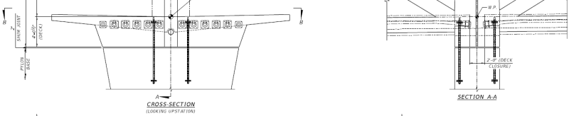
These two photos confirm (1) there is a construction joint at the interface of the walkway deck with No.12-11. (2) There are 4 vertical plastic sleeves or pipes, look like about 3" diameter to me, cast with the deck. Two on either side of No.12. There are some reinforcing steel bars, possibly for anchorages for other installation, and blue flexible small ducts or conduits, which I think could be tubes for grouting and de-airing the PT ducts in No.11.

There is nothing odd about the above items. However a construction joint if not properly prepared is a plane of weakness and can never be as strong as a monolithic construction without such joint.

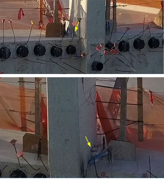
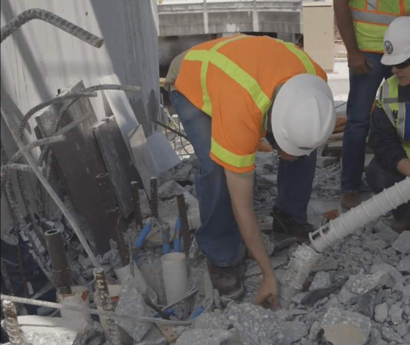
The photo below is the best I could blow up to show the anomalies in details. It has been posted several time before.
close_up_of_no.11_hole_zeqrz6.png


I find the photo odd because

(a) The No. 12 has gone but the 4 white plastic pipes are there. The tilted one appears to have suffered some damage. If No. 12 was pushed out shouldn't it take out the 4 plastic pipes too? Concrete is much harden than plastic. So such condition would suggest bottom of No.12 was disintegrating when it left its position on the deck so that the small broken concrete pieces could not drag the plastic pipes away.
(b) The No. 11 has gone too. That is expected but shouldn't we find some reinforcement that connect No.11 with the deck here. I can see one or two small size bars around the foot of the investigator who was looking at the anchorage of the bottom PT rod of No.11.
(c) The first two drawings clearly show the 4 plastic pipes cast outside No.12 but the hole shows the 4 pipes are inside it. Has part of the deck also disintegrated too to leave behind the plastic pipes intact?
(d) Between the far end vertical and tilted plastic pipe, near the investigator's foot, the surface of the hole looks remarkably clean and straight as though it was formed by formwork and not ripped out from a homogeneous concrete mass. The only possible explanation to have such good surface "finish" is this area has been boxed out when the deck was poured. There afterward the 4 plastic pipes were installed and the void was filled with second stage concrete. Nothing wrong with this construction as it happens all the time on site. However it would be suicidal to do it at a joint that has to provide restraint to arrest a huge horizontal force from No.11.
(e) The only reinforcement of the deck in this photo is at one location a couple of small bars located between the undamaged vertical pipe and investigator's foot. The amount and size don't look like proper deck reinforcement to me. SO if this area has been boxed out did the workmen trimmed the reinforcement around it too?

To assist understanding I provide my own interpretation of other items in this photos.

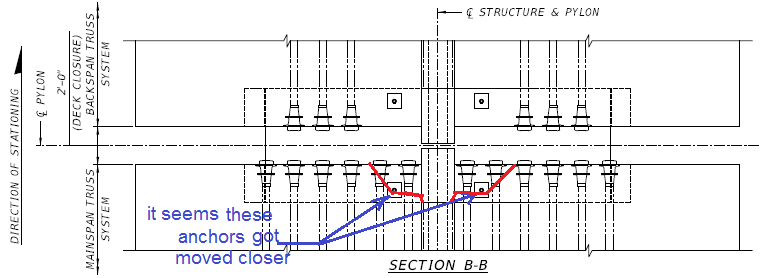
The steel plates and other plates stacked against the abutment could be the remains of the bearings. The plastic pipes could be for the holding down bolts which in the proposed drawing only two were indicated and they are a lot far away from the No. 12. Other photos show no holes for the hold down bolts. gwideman other photos has depicted what looks like two holding down bolts on the abutment but the plastic pipes can also be conduits for other services. The back of the No.12-11 area has some 5 reasonable steel bars and a few smaller bar bent against the abutment wall. They could be the rebar linking No. 12 or 11 with the deck.

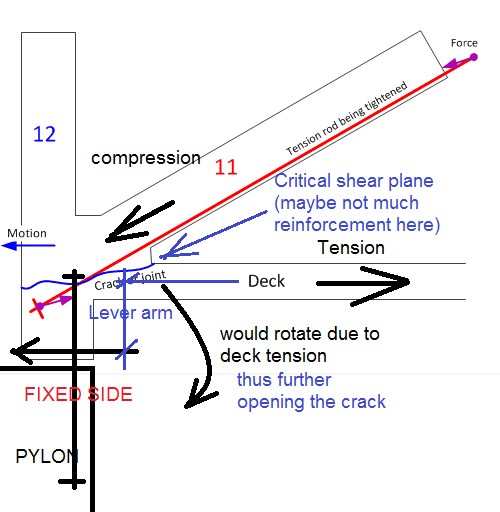
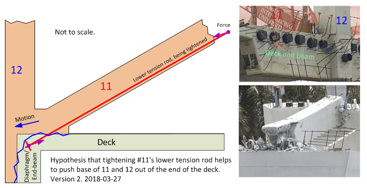
I have been haunted by the above last photo ever I saw it. Many of us talk about horizontal shear in No.11. A shear could only happen if one part moves while the other part remains stationary. Looking at the above photo and what have left in No. 11 and 12 make me think may be the supposed stationary part of the deck had moved out first to trigger the collapse. It is not really that far fetched if there is hardy any reinforcement provided to "restrain" the No.12-12 from moving outward. The concrete alone is unlikely to stop the two vertical triangular faces beneath the deck to shear off vertically. The back of No.11 could out by tension. Any reinforced concrete designer knows concrete has very resistance (in similar order as the shear resistance). The nearly untouched condition of the 4 plastic pipes does not inspire confidence the construction quality at this location. Furthermore if Tony Pipitone report were to believed during failure the tension adjustment has to increase tension, since the tension was released in the first round, then the crew was pressing their luck by pushing the No.11 out of position by increasing its axial compression.
 
jrs87 said:
I have been trying to locate them by deduction. Can we can safely assume they were not at any location obscured by a zip-tied banner? Also, the voicemail mentioned repairing cracks, not trying to arrest them. Does anyone here know of another instance of a span collapsing from its own weight after standing for a period of time? .

Better not make such assumption. The quality of this web site is we discuss facts and interpret them with our experience.

In my experience almost every concrete structure has cracks.

The bridge collapsed when the workmen were adjusting tension for the second time to fix the cracks according to a news report. It was reported the tension adjustment in the first round was completed and cracks were then discovered.
 
Updated image for the hypothesis that tightening member 11's lower PT rod could have helped to push the base of 11 and 12 out of the end of the deck.

Since a few people have reposted the earlier version of this diagram (gwideman 23 Mar 18 17:09 in Part IV), I thought I would update it to add a couple more details, and bring it in line with more recent observations people have made about various collapse photos.

gwfiu_PT_causes_11-12-slide_v2b_frnbga.png
 
Status
Not open for further replies.
Back
Top