Continue to Site

Eng-Tips is the largest engineering community on the Internet

Intelligent Work Forums for Engineering Professionals

  • Congratulations GregLocock on being selected by the Eng-Tips community for having the most helpful posts in the forums last week. Way to Go!

Miami Pedestrian Bridge, Part V 71

Status
Not open for further replies.

dik

Structural
Apr 13, 2001
25,817
This continues the discussion from Part I, II, III, and IV. Please read the other threads first:

Part I
thread815-436595
Part II
thread815-436699
Part III
thread815-436802
Part IV
thread815-436924
 
Replies continue below

Recommended for you

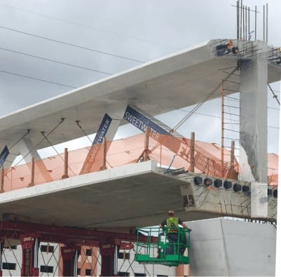
saikee119, thank you for your reply, I did not make my point clearly and as such was misunderstood. I didn't mean to imply no cracking. I was only trying to make the point that when they inspected the cracks mentioned in the voicemail, that they might have removed a banner if cracking was under it. No more, no less. I think the banners have been mentioned before in this thread.

I'm not trying to raise alarm about the cracking or suppress its significance. I agree sticking with the facts is important here. During my youth I have witnessed thousands of yards of concrete being poured and cured, and while that gives me no expertise at all, I would be the last person to say a concrete structure can be crack free. I agree this web site is of high quality, I will strive for my comments to do it justice. Sorry for the misunderstanding.
 
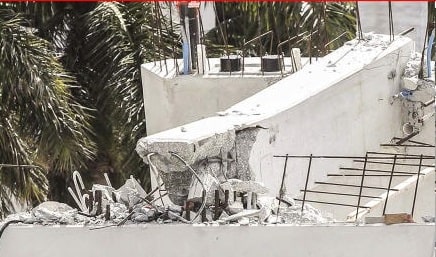
Saikee119, I agree with your comments on the above photos regarding the lack of observable reinforcement at 11 base, and the fact that the PVC pipes are nearly intact. Seems odd.

Something else to add to the discussion, and that is the fact that member 10 is seen punching through the bottom slab in the final moments of the collapse. Is this merely a random part of the process, something that is inevitable based on the geometry of the truss members? Or is the timing of this violent load reversal indicative of something else?

First figure depicts structure (member 2 -- top canopy -- member 11) viewed as an arch, with horizontal and vertical restraining forces at either end. Note member 10 in tension:
arch-3_ggehe9.jpg


Second image is with horizontal restraining force removed at north end. This needs to happen prior to member 10 going into compression:
arch-4_hxr8vg.jpg


So my question is, can we deduce anything about when 11-12 base area disintegrates, thus eliminating the horizontal restraining force Hn, by looking to see when member 10 is driven through base? Or is there no connection whatsoever?
 
TheGreenLama said:
the fact that member 10 is seen punching through the bottom slab
Could you point us to what photo or video you see this in? It doesn't look that way in the frame-by-frame posted by INCENTIVE 24 Mar 18 01:34 (Part IV)
 
saikee119 (Structural) 27 Mar 18 13:54

Very good post. About the haunting photo of the demise of member 11, I would like to point out, if not already known, that this was a screenshot from "NTSB B-Roll". I would be pleased to read your observations on the full video if you have not seen it yet. You are on to something here. Thanks.
 
TheGreenLama said:
can we deduce anything about when 11-12 base area disintegrates,

As well all know, a truss is a series of triangles. To extend a truss, just add a triangle. To shorten, just remove a triangle. What seems to have happened here is that the brace function of 11 failed. This means then next triangle in series becomes the end of structure. Of course, there is no support under next triangle, so structure falls. So I believe 11-12-deck failed before deck and canopy buckled. Joint 9-10-deck would fail after 11 as this would be where the load path would "move" to. Ditto on joint 10-11-deck. The canopy-12 joint suffered very little damage as no real load was present there. I agree with the diagram you show with bold lines outlining the true parts of the truss.
 
gwideman said:
Could you point us to what photo or video you see this in? It doesn't look that way in the frame-by-frame posted by INCENTIVE 24 Mar 18 01:34 (Part IV)

Took a while to find, but it's in Thread I, Tomfh 18 Mar 2:49, within the blown up version. When I compare this to the latest noted above by Jrs87 27 Mar 8:27, they appear to differ in that zone of the bridge. Can't explain why. Now I'm not sure what to believe!
 
Gwideman,

I realize that the remains of member 12 sitting on the pier closely resembles what member 12 looked like before the collapse, with a piece sticking below the main deck.

However if you go and look at some before and after photos using the re-bars sticking out the side of member 12, you can see that in fact the bit left on the pier was originally above where member 11 connected. There is a missing section of member 12 (the bit sticking out the end of the cross beam) which is either in the canal or is still attached to the end of the deck.

Remember - More details = better answers
Also: If you get a response it's polite to respond to it.
 
I've been stuck on Meerkat007's I-18-19:53 40ms frame-by-frame... if the 'puff' is there, then gone in 240ms, it's not the corner of the deck from a changing perspective while driving. And just noticed it looks like the canopy-to-member 12 connection breaks (goes less than 90o)... not sure if I've seen the underside of that connection - it looks like a right angle from other photos, but maybe it broke and landed that way.


I'm gathering photos for another post, but it looks as if an explosive force (like dynamite) disintegrated the 11-12 member connection/lower ends while sparing the deck and its components (even the plastic).
 
TheGreenLama said:
Took a while to find, but it's in Thread I, Tomfh 18 Mar 2:49, within the blown up version. When I compare this to the latest noted above by Jrs87 27 Mar 8:27, they appear to differ in that zone of the bridge. Can't explain why. Now I'm not sure what to believe!

I'm new to the forum, but have been following from the beginning. I see a bulge at the 11/10 intersection below the deck, but I'm fairly sure it's an illusion.
In thread 4, gwideman's photo in the 24 Mar 18 12:37 you can see the traffic signals in the eastbound lanes in the distance.

A clearer view of the signals is in INCENTIVE's post at Mar 18 01:34. You can make out the bottoms of the westbound signals and signs below the deck. It looks like one of these signals was just behind the 10-11 junction in the Tomfh photogram at the time of the collapse.

 
LittleInch... you're right - I just saw that.
Fm Meerkat007 IV-23-13:43 - Member 12 damage overlap superimposed (slick photo)...
12_damage_overlap_n7vbbv.jpg


which explains why something looked odd with no sign of the PVC pipe this photo.
The 'clean' bottom end break looks like it sheared from the deck surface (as if a second pour - other photos show a difference at this point on the 'back' of member 12). The semi-circle face of 12 is odd... like an explosive blast hit it.
12_end_break_vvevxw.jpg


This makes me wonder what happened to the small extension 'block' (bottom of 12) with PVC pipe that was on the end of the deck. Photos of the other side of pier appear to show scrape marks along sides of the face as the deck slid down, but no scraping in the middle.

This photo also answers my above question... the top of 12 is mangled but it didn't break off.. looks like rubble held in place (with rebar?). The video appears to show the 12-canopy angle decreasing like a hinge, but it landed at ~right angle... there's also some web cracking up there.
 
jrs87,

The blown up at the deck was obtained from NTSB video mentioned by members here.
 
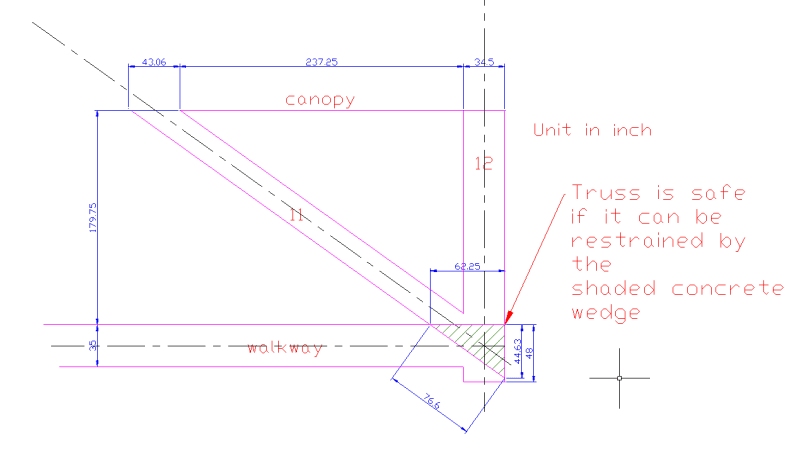
I think gwideman and I are looking at the same corner of the deck that is obviously weak for its duty. I did a CAD drawing to show how small bit of concrete there.
Capture1_ef2h5o.png


Unless enough reinforcement is provided the concrete on its own is not going to make it. The resistance area is just like a chute with two triangular shear faces on two sides and a rectangular base.

The other scenario is a horizontal shear along the top face of the deck or No. 11 went first pushing No. 12 out.

Actual failure could be a combination of several modes as depicted by gwideman.

This particular corner appears to be the weakest link. The tension adjustment action, if repeated as reported, is the trigger for its demise.
 
RCPete said:
I'm new to the forum, but have been following from the beginning. I see a bulge at the 11/10 intersection below the deck, but I'm fairly sure it's an illusion.
In thread 4, gwideman's photo in the 24 Mar 18 12:37 you can see the traffic signals in the eastbound lanes in the distance.

A clearer view of the signals is in INCENTIVE's post at Mar 18 01:34. You can make out the bottoms of the westbound signals and signs below the deck. It looks like one of these signals was just behind the 10-11 junction in the Tomfh photogram at the time of the collapse.

No doubt, it could definitely be an illusion. The series of INCENTIVE's images, however, jumps from 0.38 to 1.0 sec, missing the time in question. If you run Gwideman's video, the "possible" punching of 10 through bottom slab occurs AFTER the falling bridge has passed before the traffic signals in question.

It's also possible that the hinging of bottom slab at 10 weakens this area and allows for 10 to punch through deck; i.e it's unconnected to timing of 11-12 zone failure and more connected to deck slab failure. Pure speculation on my part.
 
Going back to look at Tomfh's post of 18 Mar 18 02:49 (Part I), I see that is shows something different from the animation frames posted on Part IV by INCENTIVE at 24 Mar 18 01:34. I have never been clear whether there are one or two (or more) dashcam videos, so maybe that's part of the difference.

At any rate, here are frames from Tomfh's animation:
gwfiu_tom_animgif_seq_kc0xsi.jpg


The feature circled in frame 1 looked to me like the north west corner of the deck, and I had dismissed it. Not sure why it disappears in frame 4.

But what I only now noticed is the bulge feature circled in frame 4 that enlarges in frame 5, and then appears to blur in frame 6. In the animation, this appears to coordinate with motion of member 11, and seems in line with 11. In short, looks like it could be 11+12 punching out the end of the deck. Too fuzzy to be 100% convincing though, of course.
 
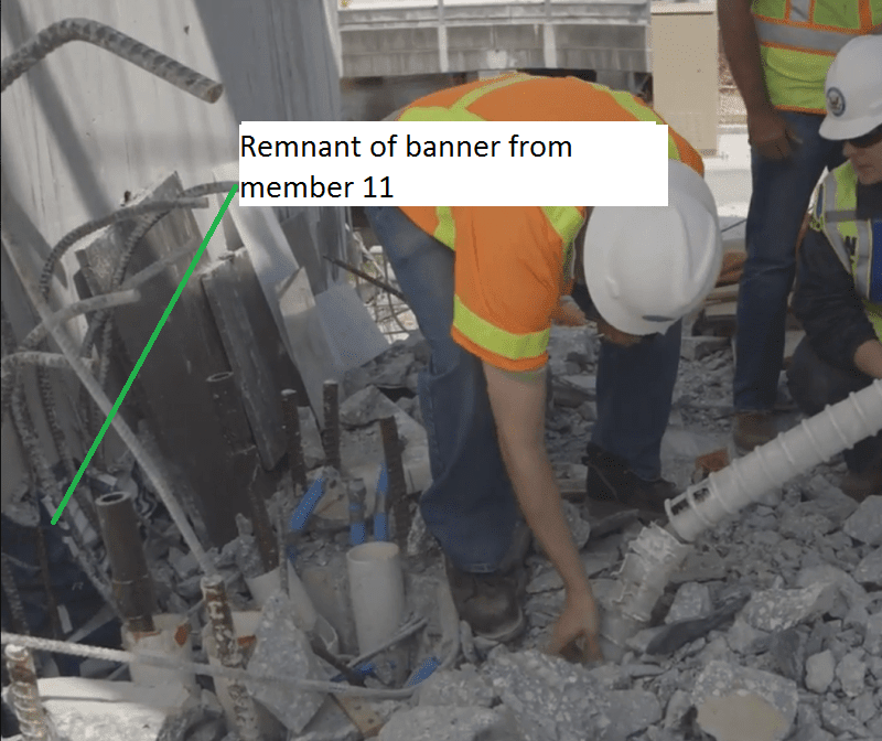
Evidence member 11 crushed base of member 12. Remnant of banner from member 11 pinned between pylon and rebar.

captioned_close_up_of_no.11_hole_zeqrz6_mrexlz.png
 
TheGreenLama said:
If you run Gwideman's video, the "possible" punching of 10 through bottom slab occurs AFTER the falling bridge has passed before the traffic signals in question.

I think I see what you are talking about. In a video posted by Tomfh in thread 1 at 18 Mar 18 02:42, I can make out a bulge just before the deck hits the ground.
 
TheGreenLamma,

I have not seen evidence of No.10 punching through the bottom slab. However when no.11 lost its restraint and could not participate in withstanding the load the deck suddenly had to resist the system by acting as a flat slab. This it couldn't do and folded. May be No.10 was able to punch through in that particular moment. I tend to think whatever happen to No. 10 is a consequence and not the root cause of the failure.

You have done very good drawings on the bridge on their supports. You are right in thinking there has to be a horizontal reaction to counterbalance the horizontal component of No.11. The designer has pinned the hope the deck will provide the Hn. It could have worked if there are sufficient concrete and reinforcement to transfer the force across or dissipate the stress.

 
gwideman said:
I have never been clear whether there are one or two

One dashcam video from large truck. Some versions of the HD video are cropped (zoomed in a lot). Since the truck was moving towards the bridge at speed, someone held the bridge size constant in the crop (he used the term "dolly"). The artifact is perspective change with constant image size. This will cause distant items to move across the frame.

Another video is not a dashcam, but a cell phone video of a traffic cam monitor.
 
TheGreenLama,

I took the liberty of making a version of your drawing. For a split second after 11 failed to hold compression, the black shows compression "path". Bending moments and shear took out areas marked in red.

arch-4_2_hxr8vg_sqhyrh.jpg
 
saikee119 (Structural) said:
Sound like a Chernobyl accident to me.

My recollection is that Chernobyl was an operational accident. This incident appears to be more construction related and similar to the Hyatt Regency collapse where unapproved modifications to the design occurred. Forensics are probably focused on the construction revisions to the bridge design.
 
Status
Not open for further replies.

Part and Inventory Search

Sponsor