Eng-Tips is the largest engineering community on the Internet

Intelligent Work Forums for Engineering Professionals

Miami Pedestrian Bridge, Part V 71

Status
Not open for further replies.

dik

Structural
Apr 13, 2001
25,564
0
36
CA
This continues the discussion from Part I, II, III, and IV. Please read the other threads first:

Part I
thread815-436595
Part II
thread815-436699
Part III
thread815-436802
Part IV
thread815-436924
 
Replies continue below

Recommended for you

Point of clarification: "the diaphragm".

A number of posters have referred to "the diaphragm". Is that the thick beam across the end of, and below, the deck, into which #12 extends at its bottom?
 
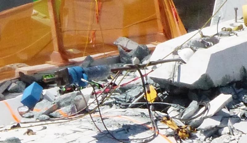
They were both accessible from the top of the blister.
tightening_btlgpn.jpg
 
I am curious as to what led to the (apparently) field-enlarged pocket for 11’s top tendon anchorages. Suggests to me that they were unable to get to the tendons for releasing the PT force, or??

Tendons too short seems highly unlikely to me. But why the need to expand the pocket?
 
Do we actually know what prestress was applied to the canopy and to the bottom deck. Have the number of strands total but 1) were all of them tensioned and 2) where they all tensioned to the maximum allowed, I assume the they would be but cannot find verification anywhere.

By the way I have done a pretty accurate wt. takeoff and excluding open conduits and ducts calculate that the total weight of the structure using 150 lb/ft3 for density of concrete and steel and 175' span is 1870 kips or 8318 kN. Reaction excluding verticals at each end and part of the canopy DL between 11 and 12 at the top would be about 887 Kips. as opposed to total reaction of about 935 kips. These loads of course are prior to applying any Load Factors which for DL alone I personally believe should be DL factor = 1.4.

I have not included added DL as per TY Lin of approximately 10 psf for a wearing course since I do not see any evidence that one was applied. The curbs that appear to have been added at each side of the walkway might add another 75 to 80 lb/ft of bridge not significant but should have added it anyway.

To continue this further lets calculate the moment in the beam using wt/ft=10.67, clear span between cL bearings = 172.5' = 10.67 x 172.5^2 /8 = 39682 k-'
With a depth of 15.8' the forces in the canopy and bottom deck are 2511 k compression and tension respectively.

Taking moments about the cL of the top flange and ignoring the diagonals we get 933 x (172.5/2) - 10.67 x(172.5/2) x (172.5/4) moment = 39682 same as above so compression and tension the same

The compression in the canopy and tension in the bottom slab are both excluding prestress in each which I do not know for sure. The two diagonals near the centre of the span are so small in area compared to the slab that their horizontal components in compression will be small and only determined by fixed joint truss analysis. The actual stress in the canopy due to DL only is 1.07 ksi. Unfactored stress in the deck without prestress is only 0.36 ksi. Due to prestress we know absolutely that the stress in the canopy was greater that 1.07 ksi and we know that the maximum stress in the slab with prestress would be a decent negative number but the slab has a gross area of 48 ft2 so it would take a huge prestress to fail it.

If the deck has equivalent of 11 = 19 x 6 tendons stressed to 70% I believe this would be about 11 x 0.7 x 4950 = 38115 kN or 8569 K so stress =-1.24 ksi due to pre-tension. Stress at the centre of the span would be -0.88 ksi after deducting tension due to dead load. This leaves added compression for full live load, tension load due to expansion of the bridge local moments etc.

In the critical first 6 feet of the deck which is the length of footprint of 11 and 12 together on the deck it is my opinion that only about 50% of the prestressing is effective in this shear zone giving only about 0.6 ksi of effective confinement stress without PT rods in 11. My opinion is that longitudinally 1 to 1.2 ksi is required and laterally 0.8 to 0.9 ksi is required for DL shear capacity without adequate deformed bars in shear to take the hor. and vert. components of 11. My opinion is only that (based on 53 years experience before retiring two years ago) and I would need to go back to the books on shear leg and confinement before making this more or less statement of fact.

With an angle of 36 degrees to the horizontal the approximate axial load in 11 would be 886/sine 34 = 1508 k so stress without PT tendons would be 1508/(22 x 24) = 2.85 ksi

With 2 tendons stressed to 250K each the stress would be 2008 / (22 x 24) = 3.8 ksi, the structure was able for a short time at least to support this stress. After release (we think) of say 250K tension the structure still stood. While releasing (we think) the second failed. Does NOT make sense.

Were they in fact increasing tension in the PT bars to close the crack instead of releasing the tension due to temporary loading or did the lack of confinement from the PT bars so weaken the deck concrete in shear that it failed along a plane about 180" long (around the footprint of 11 and 12) and on an angle through the deck to the first tensioning duct and then down to the bottom of the deck at right angle to the bottom of deck slope. Total area of this shear plane is about 180 long x 22 inches through deck = 3960 in to take the horizontal component in 11 of 1508 x cos 34 deg = 1220 k giving a shear stress of 308 psi horizontally and 887 k /3960 = 224 psi vertically on this shear plane. With what appears to be only nominal deformed bar reinforcing this shear failure is more likely to me than a combined stress failure in member 11 itself.

 
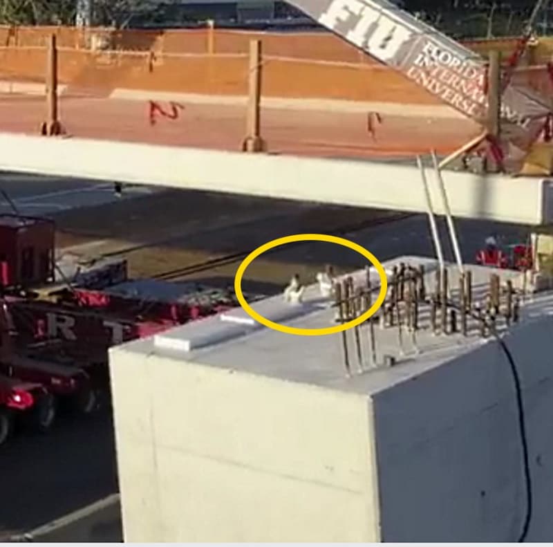
UKJim - in the photos taken during bridge placement, the same ragged edges are visible in the blisters. Whatever happened to them happened before the bridge was on the pylons. My guess is that rather than making a nice trough for the concrete pour they used spray foam or some other material to maintain access.
 
Meerkat 007
"This confuse me. For my untrained eye looks like a PT bar but from where to where ?"

I believe that it is tendon duct or utility duct from the canopy but could be wrong.
 
3DDave said:
UKJim - in the photos taken during bridge placement, the same ragged edges are visible in the blisters. Whatever happened to them happened before the bridge was on the pylons. My guess is that rather than making a nice trough for the concrete pour they used spray foam or some other material to maintain access.

Thanks. I see that now in one of the night photos. Still seems an odd thing in such a highly designed structure.
 
appster said:
Meerkat 007
"This confuse me. For my untrained eye looks like a PT bar but from where to where ?"

I believe that it is tendon duct or utility duct from the canopy but could be wrong

Looks like 11’s upper tendon to me.

Nope. That’s not it. Maybe an empty duct left from where 11’s lower tendon ripped through? Tough to say.
 
UKJIm
I was referring to the white snake going almost full length of the blister. Can only hope that the NTSB keeps a few larger pieces such as what is left of this cap and what is left of 11 and 12 to examine more closely.
 
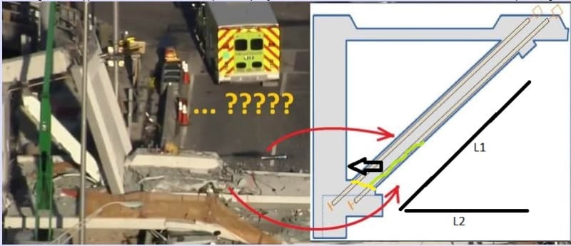
From above sketch by Meerkat 007:
Meerkat-2_t9jcci.jpg


I amended the earlier post on this question, due to confusion on my part as to which PT rod extends from top (thread is getting very long). Epoxybot reminded me it was the bottom rod. So I'll take another stab at possible explanation.

Member 11 fails in shear along yellow plane. With this primary shear failure, portion of underside of 11 spalls off along green line separating bottom PT rod from 11 and leaving it securely fixed in bottom slab. Now, significant secondary grinding occurs at base of 11 prior to bridge collapse, with vertical 12 still in place. Other members begin to fail around it--first top canopy, then finally bottom slab. Base of 12 finally gives way and 11-12 kicks out towards pier, bringing with it top PT rod. As bridge collapses to ground the distance between anchorage on top canopy and bottom slab, where bottom PT rod is still firmly anchored, shortens considerably. This could account for why bottom rod is pushed out while top is not.
 
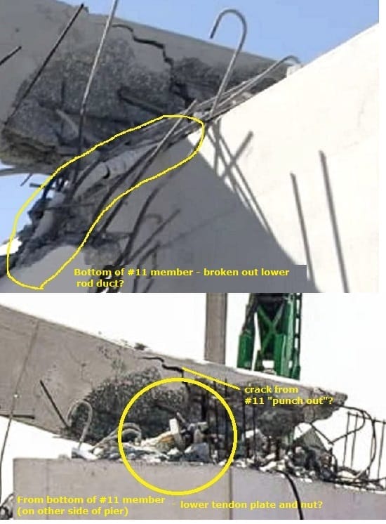
LittleInch: not sure if you were responding to me on PartIV, but my "failure" diagram isn't accurate. I had (too soon) 'assumed' the rod snapped (and didn't make changes). Below looks like #11's upper duct and rod plate/nut protruding from a shattered end. #11's upper rod/duct (not pictured, at ground level - as you already know) was stripped from the member. I'd thought this was the end of #11 leaning against the pier, but it looks like 4'-6' of concrete is missing - rebar is fairly straight (I'd expect it to get bent as #11 sheared from the deck) - if so, the contact points of #11 and #12 are still very near each other, with #11 displaced east.
11_upper_rod-duct_dntjqm.jpg


Stephen Nuchia (Electrical)26 Mar 18 21:27
"chris snyder near the end of thread IV sketches a counteracting compression force from the first diagonal of the south span. I believe that is a misunderstanding."

YES. Thank you - I understand now.. no opposing force because both mainspan and backspan are independent and not pulled together as if suspended segments held by cable stays. The backspan would be a "buttress"(?) once tied in, but not an opposing force - this would be a hokey design if it was meant to keep #11 from shearing.

LittleInch: aside from a video by Meerkat007 18-Mar-18 19:53 in 40ms segments (that may or may not show a projectile and 'dust puff' on north end), I agree the lower rod/jack could be forced out as the deck fell.

Meekat: I agree with Saikee119, that it could be an outboard duct for canopy cable, or could be the duct for the lower rod (not sure if rod/cable ducts are different diameters) - I can't tell... Here's a good photo (can see rod duct at left in shadow)
11_rod_or_outboard_cable_duct_bdcmi3.jpg


I'm going through all (about 1/2 through Part II now), but has anyone seen the dead end anchor of the #11 lower rod? Meerkat (18-Mar-18 19:53) said it appears to still be attached to the deck (under a pile of rubble). NTSB roll (Meerkat 19-Mar-18 06:48) got close when they had a measuring tape on the duct, but video didn't show the end.
 
I have been following this discussion closely. I do not do much post tensioning nor am I a bridge engineer. Which is why I haven’t commented since there are more knowledgeable people to do it. But I wanted to agree and at the same time disagree with the above regarding the DL. For a DL only load combination 1.4 factor would be a more appropriate one for design. However I believe if we’re evaluating a complete collapse then a factor of 1.0 should be more accurate, no?
 
LITTLEINCH said:
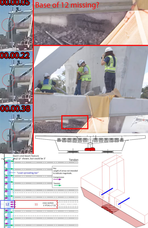
Flicking through some of the past posts I wonder / hope that someone is searching the bottom of the canal. There seems to be a big chunk of the bottom of member 12 missing....

In the photos, it looks like you can see rebar going through the base of member 12 with missing concrete all around that goes through the entire member. Could just be from hitting the ground or contact with the pylon. Also still unsure if the large object that protrudes under half a second before the collapse is just the corner of the deck or an illusion. Photo quality is just to low, won't know anything for sure till NTSB releases more info.

BASE_12_GONE_rnu7bf.jpg
 
Mjkkb2,

I agree 100% with you. That was what I do for root cause analyses. Load factor is for design. This is actual analysis or simulation to establish out the cause of the collapse.
 
Here is the likely suspect for the spalling on the inside face at the base of the diaphragm,

Diaphram_Spall_gxq8g6.jpg


In very slow motion, the blob on the end of the deck rotates upwards as the deck pitches forward. I think it is just the corner of the deck.
 
gwideman: "Where is that photo from?"

Part IV Incentive 24 Mar 23:01.. have seen others (Meerkat 23 Mar 17:53 and elsewhere online) but this was highest res. He's got good points there - all of it sticks in my mind (esp 'blowout' residue on that beam by the canal). Just noticed how rebar is bent out bottom of #12 (assume when it got pushed/broke from end beam), but ~straight from bottom of 11.

Been there a while, but just listened to this from Tony Pipitone.
Said they were tightening #11 when it failed, and that WORK was being done, not a 'stress test' (~3:30-4:40), among other things.
 
Status
Not open for further replies.
Back
Top