Eng-Tips is the largest engineering community on the Internet

Intelligent Work Forums for Engineering Professionals

  • Congratulations waross on being selected by the Tek-Tips community for having the most helpful posts in the forums last week. Way to Go!

Miami Pedestrian Bridge, Part VI 31

Status
Not open for further replies.
hokie66 et al.,

Let's presume what you say is true, that the #4 @ 12" (typical) are not shear reinforcement, but are "column ties". That thought, of using column ties for structural members within a bridge span, makes the hair on the back of my neck stand up! Should we expect a full A), B), C), accounting of the design assumptions made when the NTSB issues its final report?
 
Yes, we should expect that. But we will have to wait a long time, I think a year or more.

I believe the philosophy was to design a typical truss bridge, but using concrete instead of the usual choice of steel. No doubt that philosophy is now regretted, along with the chosen structural form of using wide plates rather than compact members as chords.
 
I believe the horizontal reinforcing in diagonal 11 are just column ties since if they were shear reinforcing they would be spaced at d/2 where d when the p t is in place can be taken at no less that .8 x t =19.2 inches making d/2 9.6 inches. Without the pt force, d is approximately 21 inches calling for spacing of 10.5 inches center. The d/2 requirement is to make sure a potential crack is intersected by at least one tie.
In a two force truss, there would be no shear in diagonals since the ends are considered pinned. This is not a true two force member since the ends have fixity. An analysis of the truss with ends fixed would give some moments in the diagonal and therefore shear, though I doubt it would be much. Equal to about the difference in moment at the end divided by the length.
 
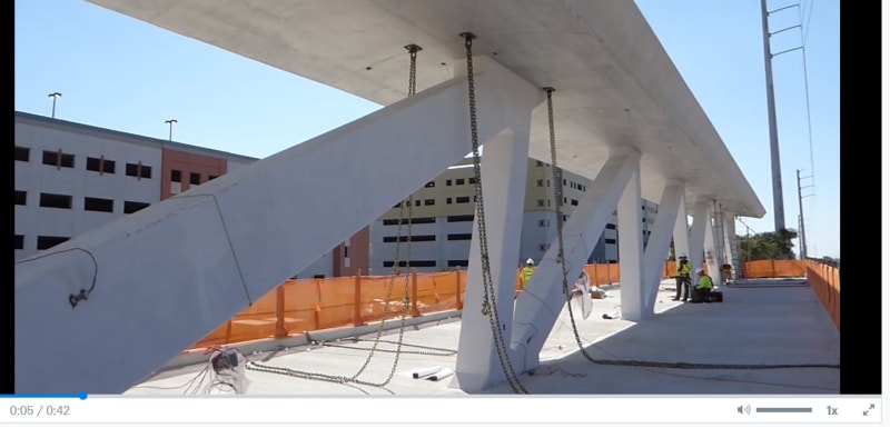
Interesting videos showing span fully suspended from deck ends on temporary shorings before move. Interesting mainly because span may have had an opportunity to collapse at this stage. I'm curious if PT rods for 11 and 2 were stressed while span was suspended like this.


Just a tidbit I would like to throw out there.

(To fellow posters, thank you for your great posts, I feel better after studying them.)
 
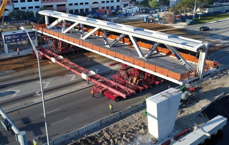
Correct me if I'm wrong, but after reviewing photos and videos here, it appears that both faces of member 11 are completely wrapped in that banner, "City of Sweetwater, FIU, Florida International University." This banner would obscure any shear cracks that would've developed in member 11 warning of a potential failure.
 

jrs87 (Mechanical)30 Apr 18 13:12
"Interesting videos showing span fully suspended from deck ends on temporary shorings before move. Interesting mainly because span may have had an opportunity to collapse at this stage."

I thought about about this a while back. When the truss columns were poured, there would have been a low level concrete bonding from deck to diagonals/columns. Since there was little stress on said construction joint at that time, it most likely stayed bonded. That all changed during the seismic type twisting that occurred in transit, while one corner of deck was on sidewalk, & the other was rising over the street curb. My best guess is about 10" rise at each corner. It would have debonded for sure at that time.
 
TheGreenLama
"Correct me if I'm wrong, but after reviewing photos and videos here, it appears that both faces of member 11 are completely wrapped in that banner, "City of Sweetwater, FIU, Florida International University." This banner would obscure any shear cracks that would've developed in member 11 warning of a potential failure."

I'll go one better....
During transport, there was a stoppage for an extended period of time, while 3-4 workers inspected the south end @ #1/#2. They did this 2x, that is to say...on deck, down, & back up again. There was no evidence of inspection on the north end. Interestingly enough, one of the drone videos shows a rapidly flashing light on north end #11 bottom/fillet during this time. After wondering about all this for a while, I have to wonder if they got sensor wires crossed fromm north to south. It would explain a lot, because the south end was very robust by comparison to north, & likely didn't have any issues.
 
To TheGreenlama:

What temporary supports is Step 3 talking about?


Nice catch. It appears that the construction sequence drawings are "a little" "incomplete" because they do not mention all the needed info:

For instance, a "good" erection drawing should mention the concrete strength needed to move the bridge. Otherwise, it will be assumed that 6000 psi is enough. So, we are missing a line saying : "After the concrete reaches 8500 psi, you can move the bridge"

Also, It is possible that the reference to the "temporary supports" is something left from a preliminary erection sequence. I did not see any other depiction of temporary supports in the plans. It is also possible that a set of updates after 4/4/17 exists that we do not know about.

Another thing, the shims supporting the span at pier 2, how do they look like?, how thick? How many? where are they? Because that affects the forces at the 11/12 node. No info in the Erection plans.

Finally, the removal of the PT bars in members 2 and 11 is not in the erection drawings. It is in the drawing that shows the PT bars in one of the notes. That is not really "acceptable".

So, are these the final plans existing before the sad day?

Thanks

Live long and prosper.

 
Reply to The Mad Spaniard (Structural) 30 Apr 18 17:09

I believe is was Retiredat46 that questioned "Step 3". Very good, Retiredat46. The beams connecting the transports is probably why middle of the cross section support is not seen.

I know this thread is way too long, but conversely, the more it continues, the more it uncovers a load a apparent weaknesses in this project.

Reply to TheGreenLama about banners

Banners being installed March 9, 2018 Video 1 Link

Video 2 (Please excuse worker for temporarily not wearing hardhat.) Link

Some type of sensor may be attached to member 11 under banner. March 9 photo of member 2 below. (Not a camera, cameras are on sticks in corner of orange mesh)

Member_2_March_9_2018_i1wpoi.jpg


Reply to Cutterhead (Industrial) 30 Apr 18 15:39

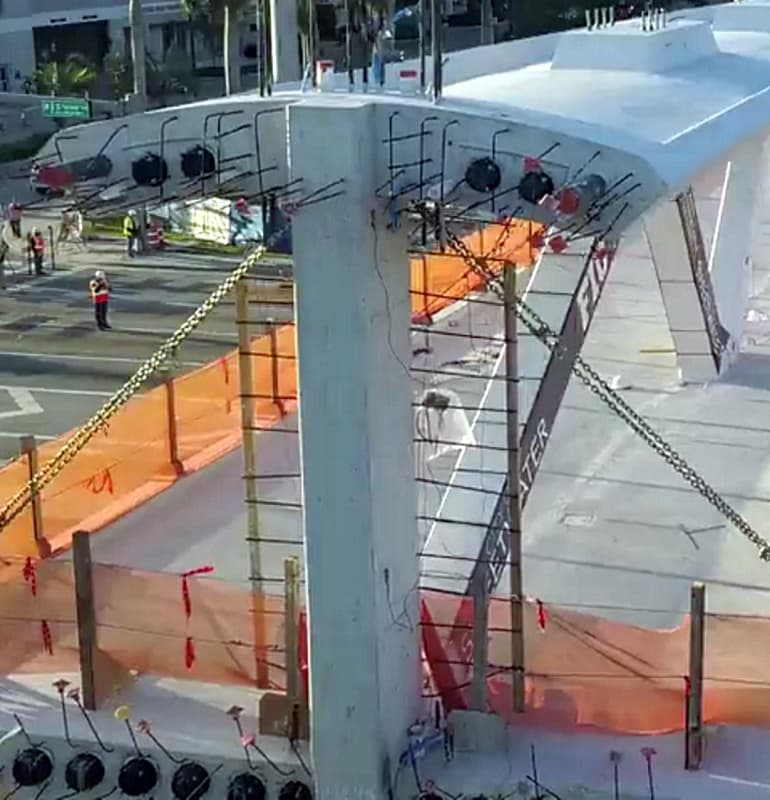
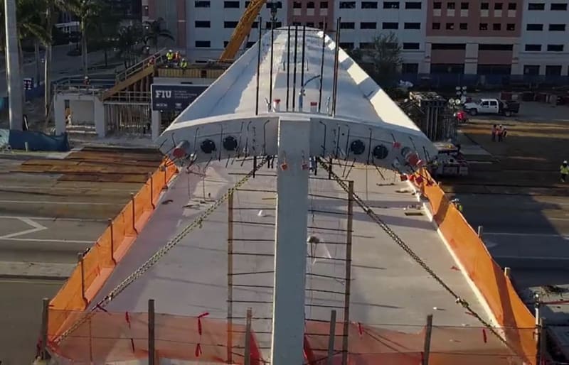
Perhaps chains attached to span were meant to address "seismic" stress during move. How tight were those chains tensioned? Could they have caused cracks at the 90 degree intersection between member and deck?
 
hokie66 said:
As with many structures, the key is in the connections.
A good discussion of general connection failures is in the Appendix of the Latvian Maxima collapse analysis, starting on page 23.
An excerpt: "Connections are mostly guessed, leading to fatal flaws in the design."
Interesting to see discussion on this now.

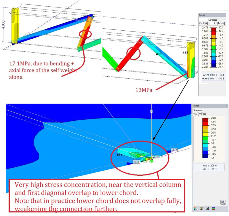
The engineer (Toomas Kaljas) said computer programs are good for designing loads and members, but many don't analyze connection strength. He immediately saw the the cause as a weak 11,12,deck connection. His 3D analysis of the span is here.
He said a 2D analysis wouldn't show the problem.

=> I don't understand why the stress at #12 is so much different from #1 (must be from the asymmetrical design, but it's drastic compared to the difference in X/Y load forces).

01-FIU_bridge_stress-j_mruyvy.jpg
 
A question that has been in my mind, about the grouting of #2 and #11. It might be possible to see from the sequence of photos whether the work being done on the day of the failure was a late modification instead of the planned de-stressing.

The construction specifications say that the PT bars in #2 and #11 "will not be grouted", and it's clear in the videos of the span being moved that #2 and #11 were left ungrouted (while other blisters have been filled in). On the day of the bridge failure both #2 and #11 are obviously open. But some photos seem to suggest that in the intervening time, #2 and #11 were grouted, as though the planned work was already complete, and only later chiseled out again. (Also there is a chisel clearly visible in post-failure photos, as many commenters pointed out). The photos below were posted by LittleInch on the V thread at 29 Mar 18 09:13. They seem to show the span set in place and with all blisters grouted, including 2 and 11. Can others judge whether this is just an optical illusion? It seems important to figure out which.
Stress_points_cgmqdt_dllmnw_lwwksk.jpg

stess_points1_qh9bbm_rvlgac_y5rvyy.jpg
 
jasm said:
"Will not be grouted"

Grouting in plans refers to bar duct, not blister. The bars are also not be be removed. Which brings up a point, what will prevent bars from corroding if they are not grouted? Does it matter that non stressed bars will corrode over time?
 

Nice work by Toomas Kaljas. It gives a big hint of the magnitude of the self-weight forces in the structure.

However, it may not reflect the effect of the top and bottom PT which may add bending moments to the intersection between 11 and 12. Maybe he will add those effects in the future.

In addition, I expect a large (tranverse to the deck and in the plane of the deck) internal tensile force in the end diaphragm due to the forces from the deck longitudinal tendon anchors. That tensile force is added to whatever happens at the node. All this is critical for the shear friction analysis of the node.

All these forces can only be really obtained by a 3-D analysis whether be FEM or three-dimensional grillage. Also, additional secondary moments, due to non-linear geometric behaviour (buckling) may be of importance. Who knows? But this is not a "simple" structure for sure.

Also, we should all remember that the node concrete side faces are compromised by the vertical PT holes and the drainage pipe hole. There may be not much concrete "meat" there or crossing rebar to accommodate all the forces applied by members 11 and 12.

If after all of this, node 11-12 is ok, time to focus on top node 11-10. But not yet...

Good hunting....

 
jasm said:
They seem to show the span set in place and with all blisters grouted, including 2 and 11. Can others judge whether this is just an optical illusion?
The best photo I found is this (full res attached). It appears 2 and 11 blisters are open - which would be necessary to tighten the rods before transport (other blisters appear sealed).
100-BEST-fiu_bridge_installation_ivqsce.jpg


This has audio interview with investigative reporter Tony Pipitone at beginning. It specifies if "post-tensioning" is 'loosening' or 'tightening' (this has been confusing all along). He says the span was set in place and "tension was released on those outer diagonal trusses" soon after (~3:30), then about cracks and "adding tension" to the rods. At ~4:30 he says this was NOT a stress test, but actual work to address something that had been discussed at the meeting that morning.

This is a good video by him saying the south end was adjusted then the north 3/4 done when it failed. There's a "puff" mentioned but think consensus here is that's the northwest corner of the deck, but after that a dark triangle below it appears which consensus seems is #12 kicking out (you can see this better in Part V - video loop gwideman 28 Mar 18 07:00, and frame grabs TheGreenLama 28 Mar 18 16:55)

This article specifically says the south side was adjusted (both rods), one rod of north side adjusted, and then failure when remaining north rod adjusted (upper with jack)

 
Where are these so-called "full res" photos coming from? Even if someone had used a six year old iPhone they would have gotten a higher-resolution image than the one that was just posted above (and I do mean the attached "full res" image).

John R. Baker, P.E. (ret)
EX-Product 'Evangelist'
Irvine, CA
Siemens PLM:
UG/NX Museum:

The secret of life is not finding someone to live with
It's finding someone you can't live without
 
John R. Baker said:
Where are these so-called "full res" photos coming from?
LOL... I (and assume others) pull them from news articles. To find photos, I search a topic on Google images, select photo, "visit" site, then "save image" to check res and hope for best. Eng-tips reduces res on thread, so attached is higher (though maybe not much). So you takes what you can get...

I looked a lot for blister photos before and there aren't many. Maybe someone here has better, but I can [barely] see the open blisters (I wanted to confirm this too).
I thought someone mentioned a drone video, but maybe not (and not sure if it was before/after transport or collapse.

 
The attached "full res" is 1140x723 pixels across, with no metadata, suggesting a screen-capture from a news website that's been cropped a little. I don't think the intent was to imply it's an original, although, for the photo-savvy, the term "full res" is normally taken to mean the original photo without cropping. A forgivable misuse of terminology, if we accept in this context that not everyone knows or cares how cameras work. I think Chris is giving us the best he's got, that's all. Not enough pixels for me to make out grouting on any of the blister, however.

STF
 
My question was intended to be a bit rhetorical ;-)

That being said, the context in which I asked it was that of being a photographer. My point is that my first digital camera, a Canon PowerShot S10, which I purchased 18 years ago, had a resolution that was more than TWICE that of your attached "full res" image. I know you had no say in this, just that it amuses me that it appears to be difficult to find truly high-res images out there.

John R. Baker, P.E. (ret)
EX-Product 'Evangelist'
Irvine, CA
Siemens PLM:
UG/NX Museum:

The secret of life is not finding someone to live with
It's finding someone you can't live without
 
See the image linked to in the following:

epoxybot (Structural) 17 Mar 18 04:22

Chris - most all investigation has been done in the previous pages; most on the first page. I would have linked to the photo directly, but this topic was shut off for a while because of redundant posting. There is a lot to read, but it's worth while.
 
Status
Not open for further replies.
Back
Top