Eng-Tips is the largest engineering community on the Internet

Intelligent Work Forums for Engineering Professionals

Miami Pedestrian Bridge, Part VIII 80

Status
Not open for further replies.

JAE

Structural
Jun 27, 2000
15,432
0
36
US
A continuation of our discussion of this failure. Best to read the other threads first to avoid rehashing things already discussed.

Part I
thread815-436595

Part II
thread815-436699

Part III
thread815-436802

Part IV
thread815-436924

Part V
thread815-437029

Part VI
thread815-438451

Part VII
thread815-438966


Check out Eng-Tips Forum's Policies here:
faq731-376
 
Replies continue below

Recommended for you

Apparently when first discovered the cracking problem was at its early stage and progressively got worse with time. The post-tensioning adjustment work carried out prior to the collapse could have exacerbated the situation too.

On the last day when photographs were take if a competent PE were to examine the crack width on the deck at the location with Member 11&12 (say it is just 1"), ascertain the maximum thickness he could measure the deck (which is about 48.875" according to the drawings available publicly now) and calculate the strain=deflection/thickness to arrive at the cracking strain of 1/48.875= 0.020 he would be able to stop the construction work citing the maximum strain of 0.003 for concrete at the ultimate limit state of collapse had been exceeded. 0.003 maximum concrete strain at collapse limit state is used by all ACI reinforced concrete codes say 318, 349 and 350. European codes uses 0.0035 so the magnitude is pretty universal. The cracking location did not failed by pure compression but a combination of tension and shear. However there is little possibility that the bridge at the cracking location, which right at the bearing support, could still be deemed serviceable.

To me the failing of the design isn't much to do with the amount of tendons and reinforcement in the Members 11&12 or in the deck but the assumption that the connection point would be rigid in the structural analysis not being realized or achieved in the field. The design does not allow sufficient space to deploy enough concrete and reinforcement there to ensure the two to remain monolithically connected when under load. The photographic evidence shows the Member 11&12 sheared off over the top of the longitudinal post tensioning tendons system of the deck which dropped to the ground with little damage.
 
I'm following this story from the very beginning - and my opinion do not change - the bridge was under designed, with way too low safety factors used in the calculations or computer model, and with apparent gross error in the design, which is missing analyses of the truss in the construction stage, i.e. long truss erected and supported, without short truss in place. The short truss, abutting the long one, is taking the horizontal load off the critical node, and reducing the shear to the level which it was designed for, but unfortunately not for the shear during movement and placement on the piers. The photographs of the cracks taken prior to the collapse are the most disturbing, as any marginally competent engineer should know that the reinforcement was already yielding, so the collapse was imminent. Which brings another very disturbing question - who had seen these "secret" photographs, and what was their action? Perhaps answering this is a subject of ongoing investigation?
 
wiktor said:
missing analyses of the truss in the construction stage

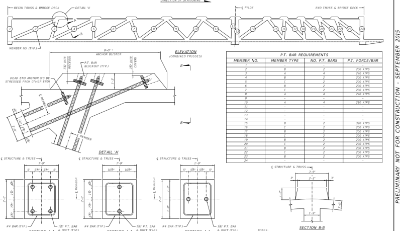
Since the bridge has high strength tendons inside the vertical and sloping truss members and a table is enclosed in the MCM/FIGG proposal document, based on which the bridge contract was awarded, it would be difficult for the public to suggest the major calculation is lacking during construction.

Screenshot_from_2019-03-26_10-45-26_jtdypp.png


The above tendon forces are expected to be installed in the bridge at its final position for the working condition. Before the bridge was lifted off its casting position part of the tendon forces would have been applied to give strength to the bridge for its relocation operation. When the bridge had been lowered into the abutments the tendon forces would have to be adjusted. Indeed the bridge collapsed during the tendon adjustment phase.

It would be unimaginable that calculation was not performed in each stage to arrive at the amount of tendon forces needed. Thus the investigator can anticipate there will be essential calculation performed. Whether the computation is correct or adequate for the purpose is another matter.

Personally the evidence of cracks, by the geometrical formation, extent, severity and location, indicate a connection failure. Unlike structural steel, where one can perform calculation on each connection, in reinforced concrete the connection calculation is rarely done. It is like forming a hole in a concrete slab the designer is expected to detail four trimmer bars across the corners. An experienced designer would know something is needed to beef up this connection if one examines its stress path. Whenever structural calculation is performed on reinforced concrete each joint will have to be assumed rigid and monolithic so that the forces, bending moments and shears are held in equilibrium by the members at that nodal point. I expect the designer in this case to be criticized for failing to realize the basic design assumption in the field.

I do have sympathy for the designer as checking the structural adequacy of a connection is not routine in reinforced concrete design. The design with both reinforcing steel and post tensioning tendons is respectable, the bridge arrangement is elegant and the fake stayed cable (using steel pipes) is innovative. The bridge would have worked if the designer was given more room to put a bit more concrete and rebar at the cracked location to dissipate the highest stresses in the structure. He could also had insisted the post tension anchors of the Member 11&12 and the deck to be structurally linked to those in the deck locally, say by a gusset plate or by welding.

Engineers learn from mistakes. There are many good lessons to be learned from this bridge.
 
saikee119 said:
I do have sympathy for the designer as checking the structural adequacy of a connection is not routine in reinforced concrete design.

I've stopped commenting on this thread, but I couldn't let this pass. This is complete BS! Any qualified bridge engineer does this routinely.
 
Just to be sure we are on the same wave length I am talking the rebar inside Member 11&12 having sufficient development length in the deck and vice versa.

The deck has horizontal rows of post tensioning tendons in two directions so the concrete is under high compression axially and transversely making it a stiff 2D plate. Similarly Member 11 is axially compressed to be a lot stiffer than normal reinforced concrete. During the relocation operation the bridge was supported with the two ends as cantilevers making Member 11 a tension member temporarily so stress reversal occurred too and that I suspect is the basis for post tension adjustments. However there is a thin layer of concrete in the deck above the post tension tendons connecting with the Member 11&12. This reinforced concrete layer is relatively free from the post tensioning effect and not subjected to the same stress intensity as the Member 11 or the main deck. Member 11&12 pushes this layer outward while the deck's post tensioning tendons pulls it inward.

To analyse this connection properly one will need to assume several modes of failure and compute the shear and tensile resistances of the concrete and rebar across the breaking surfaces. The capacity of the connection is the mode that requires the least breaking force or along the line of the least resistance. May be it is done routinely but it isn't a topic I am familiar with in the ACI or AASHTO codes in USA or the EU codes, other than checking the development lengths of the embedded rebar which tells us only the tensile contribution from the reinforcement at limit state. To make it more interesting there is a large diameter 8" drainage pipe embedded with a number of grouting ducts making the continuity of rebar very challenging at this location. The failed bridge has evidence suggesting these embedded items could have been points of weakness.

If the above connection has enough concrete or rebar it would not have sustained the cracks well exceeding the limit state collapse strain.
 
@saikee119
Just to be on the same wave length - I'm 100% sure that something was amiss in the analyses of the temporary condition. The proof landed on the highway, so the only question is how it happened.
The bottom deck tendons were to far away from member 11 to contain the horizontal force from #11 (i.e. shear in between diagonal and the deck) - actually depending on the actual sequence of tensioning, this shear could be increased as result of post-tensioning.

" May be it is done routinely but it isn't a topic I am familiar with in the ACI or AASHTO codes in USA or the EU codes, other than checking the development lengths of the embedded rebar which tells us only the tensile contribution from the reinforcement at limit state."

Both ACI and AASHTO, and Eurocodes are great "cookbooks". Unfortunately, the familiarity with the cookbook doesn't make a great chef.

"Personally the evidence of cracks, by the geometrical formation, extent, severity and location, indicate a connection failure. Unlike structural steel, where one can perform calculation on each connection, in reinforced concrete the connection calculation is rarely done."

The connections are always analysed, when design is done by a competent engineer - period.
 
Wiktor,

I like the word "competent" used by you.

I am not sure your definition of temporary condition as I thought the bridge was already in its final position and structurally independent. I suppose we could classify it as one of the construction phases because once the rest of the abutments are constructed and the fake stay cables fitted the bridge might survive with the benefit of additional restraints and some small structural contribution from the steel pipes. The cracked section would then be constrained and requires a local but substantial strengthening scheme.

Bearing in mind Member 11 had a complete stress reversal from being in pure tension, as a cantilever during the transportation, changed to 100% compression after being dropped onto the abutment there could be some dynamic stresses overlooked. My point is the bridge was in its final position and had survived all the previous temporary conditions. It would be nearly impossible to find which temporary condition had gone amiss.

We all know design codes are just good engineering practice to follow. We can put in more than the code mandates but not less. If we follow the code to the full and interpret it as every competent designer a failure is not our fault but state of our knowledge needs to be improved. In that way the code protects us. As an example we specify the adequate cover and use the right mix to protect the rebar to withstand a 1 hour fire but the component fails then we do not expected to be prosecuted if the materials were up to the standard. My respect of the design codes is probably due to having used about a dozen of national reinforced concrete design codes in my time and did not find them vary significantly from each other.
 
Wiktor said:
...The short truss, abutting the long one, is taking the horizontal load off the critical node, and reducing the shear to the level which it was designed for, but unfortunately not for the shear during movement and placement on the piers...

The bridge looks like this should be so on the outside, but I don't think that there is much evidence that it was actually designed to work like that. The construction drawings so far available appear to show that the two trusses are structurally independent of each other. I think that it is likely that, had the long truss lasted until the short one was in place, its eventual failure would have just kicked the short truss off of the central pier, and both would have fallen.

--Bob K.
 
With regard to NTSB finding (2) the public like ourselves do not have access to the design calculation and wouldn't know what demand (load) was estimated by the designer at the above nodal point. One would have thought the dead weight of the structure is hard to underestimate whereas the wind, snow, thermal, shrinkage, creep, pedestrian traffic and seismic loads were not playing much a role at the time of collapse a probable culprit of load underestimation could be construction-induced stress sustained when the bridge was moved from the casting position to the collapsed position.

The final report takes time because it has to demonstrate no stone unturned and for completeness like the materials tested are in compliance or not, explanation of failures of other parts could be consequential , a list of contributory or non-threatening construction defects found, certain minor oversights or omissions in the design discovered here or there etc, etc.

The combination of Finding (1) and (3), to some of us, has already defined the root cause of failure.

The discussion of the last few posts is on the subject whether the failed critical section, as stated in NTSB Finding (1), is routinely analysed by a competent bridge designer or not.
 
...whether the failed critical section, as stated in NTSB Finding (1), is routinely analysed by a competent bridge designer or not.

With a totally unique bridge like this, there is no "routine" about the design at all.

So asking if engineers routinely check a non-routine connection is a bit of a weird question.

The question should be: Did the design engineer perceive that the diagonal/vertical strut connection to the horizontal deck was very unique and therefore demanded very focused and special design attention?

Check out Eng-Tips Forum's Policies here:
faq731-376
 
Too much focus on the node where the collapse initiated, and too little focus on the structural concept. This was not just a truss with axial members, it was a concrete frame, and the flexural behavior of the members and joints was not understood by the designers. As well, internal restraints led to cracking which was ignored. Shrinkage cracking is often inconsequential to strength, but that was not the case here. The critical mistake which was made was not to load test the structure while they had it on the ground. For a structural type which was unprecedented, that should have been obvious, at least it is in hindsight.
 
saikee119 said:
When the bridge had been lowered into the abutments the tendon forces would have to be adjusted. Indeed the bridge collapsed during the tendon adjustment phase.

You're way late and seem to have missed a lot of important information that has already been covered.

The PT rods in 2 and 11 were there to support the cantilevered ends of the bridge during movement. The first thing they did after placing the bridge was removing the tension in the rods inside those members. The general wisdom is that the crew was re-tightening the PT rods in member 11 when failure occurred, even though those rods were never supposed to be tensioned once the bridge was in position. In other words, they had placed the bridge and released the tension in the PT rods as per the design and then decided later to re-tension them again, allegedly with the intent to see if it would close the cracks.

 
LionelHutz,

While I admit not having read the post but I did start when the thread first commenced and occasionally came back when NTSB released the findings periodically.

To make sure no misinterpretation I have never implied the tendon adjustment in Member 11 causing the failure because I used the word "tendon adjustment phase". The video everybody can see when the bridge collapsed had a workman adjusting the tendon at the opposite end of Member 11.

As regard to whether the tendon forces were removed, relaxed or re-applied I can only go about it according to the table in the drawing showing the PT Bar tension requirement I posted on 26 Mar 19 12:09. In it Member 11 show no force required. Thus if force were applied and then removed in any member that to me is the tension adjustment phase.

The FIU bridge collapse has the hallmark of the West Gate Bridge collapse in Melbourne Australia in 1970. It was a steel box girder bridge with a large misalignment when two parts joined together. The workmen placed heavy concrete blocks to force the two parts together and the bridge collapsed as a consequence. Another attempt by the site people doing their own things not in accordance with good engineering practice or per design drawing.
 
hokie66 said:
...The critical mistake which was made was not to load test the structure while they had it on the ground. For a structural type which was unprecedented, that should have been obvious, at least it is in hindsight.

That sounds like a no-brainer in, as you say, hindsight. But I wonder what that static testing might have looked like in practice. Clearly they'd support the bridge at each end to simulate the actual abutments. For the mass, would they use gravel or sandbags or water bladders?

I can imagine that the idea of a static test would be somewhat unpalatable to the developers. For one, the idea that it needs testing at all kind of casts doubt on the design--aren't these the world experts in ABC bridge designs? For another, it would inevitably become a public spectacle, and anything less than resounding success would reflect poorly on all involved. Of course, both of these rationales are in fact excellent reasons to conduct such a test. Anything that can be destroyed by the truth deserves to be destroyed.

Oddly enough, when I google "bridge static load test," one of the strongest hits is for this paper on a mobile testing system developed by--wait for it--the Florida DOT. Another interesting hit was this paper about using, among other things, US Army M60 battle tanks. Which suggests that the guy who crashed a Bobcat skid-steer loader through the deck of a different pedestrian bridge might have been on the right track.
 
saikee119 - Well, they reported that the PT rods were adjusted to their final tensions on the same day they placed the bridge, so the only direction they could be going on the day of the failure was to be applying tension again. This was all covered in the threads.
 
hpaircraft,
Yes, they could have used water or sand. Plenty of both in Miami.

The load testing in the FDOT paper is really a load rating test. They are not fully loading these existing bridges, but rather using instrumentation to rate the capacities.

The M60 tanks are a bit of a reach. Another thread here about a bridge in Colombia shows them driving a line of loaded dump trucks onto a completed cable stayed highway bridge. That's a real test, but not what I was looking for.
 
The configuration of this bridge would preclude the use of tanks or trucks. Of course, for a pedestrian bridge either would be significantly more concentrated load than it was designed for. Very few bridges are ever tested for capacity. A few are tested for deflection at something well below the expected capacity, to estimate their capacity, usually after many years of service and significant deterioration.
 
Status
Not open for further replies.
Back
Top