Continue to Site

Eng-Tips is the largest engineering community on the Internet

Intelligent Work Forums for Engineering Professionals

  • Congratulations KootK on being selected by the Eng-Tips community for having the most helpful posts in the forums last week. Way to Go!

Miami Pedestrian Bridge, Part VIII 80

Status
Not open for further replies.

JAE

Structural
Jun 27, 2000
15,444
A continuation of our discussion of this failure. Best to read the other threads first to avoid rehashing things already discussed.

Part I
thread815-436595

Part II
thread815-436699

Part III
thread815-436802

Part IV
thread815-436924

Part V
thread815-437029

Part VI
thread815-438451

Part VII
thread815-438966


Check out Eng-Tips Forum's Policies here:
faq731-376
 
Replies continue below

Recommended for you

I didn't suggest trucks or tanks. What should/could have been done is a load test with static mass, such as sand or water as suggested. This is quite common in building structures, if not for bridges. This was not just a bridge, it was a never before attempted structural design.
 
The bridge, according to the design brief, is to carry a live load of 90 psf (pound per sq ft). Since water has a unit weight of 62.4 pound per cubic ft the pedestrian traffic this bridge can carry is equivalent to a layer of water of just 17" deep. Forget about the load test, army tank, lorries....
 
Why do you say that, saikee? I suspect that 17" of water would have told the story easily, as the bridge actually failed under its own load. But the load test would have needed to be conducted in accordance with US standards for load testing.
 
hokie66,

Like HotRod10 said we would test a whole bridge if we need to ascertain its capacity. This is usually done if understrength or defective construction, say a wrong mix has been poured or the rebar fails the strength test, is suspected or its structural details unavailable due to old age.

If we do want to test this bridge all we need is to erect a 24" high watertight barrier and pour water to a depth of 17". Is that the information everybody is seeking?

Like you said this bridge couldn't even support itself let alone put anything on it.

I am just being practical. This bridge cannot be tested at its casting position because when it is transferred its final position the lifting operation can inflict damage after it has passed the load test. The bridge could have been tested if it didn't collapse. However by then who would bother if it works?

There exists procedures with which we can test a bridge structure but that is not a normal requirement in any bridge construction as it will be expensive relative to the cost of the structure. Let's say FIU is clever enough to write a clause in the contract to mandate the builder to carry out a load test. We still be exactly what we are today because the load test would only be of value to FIU when it is fully complete and not just one span when it collapsed.
 
There is no reason why it could not have been tested where it was built. Damage by transport is highly speculative. And this span had to work on its own, not as part of a continuous bridge.
 
hokie66 said:
Damage by transport is highly speculative

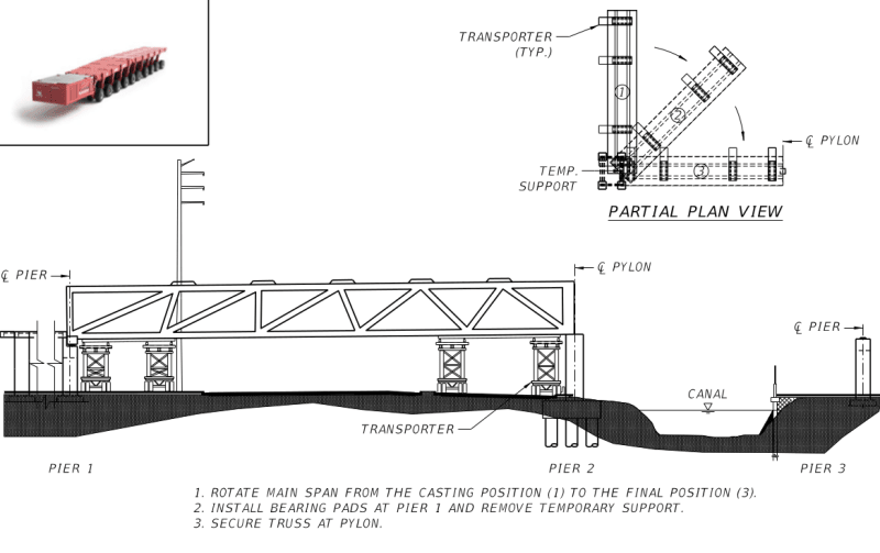
It is speculative but not highly because had the bridge been transported as per original design the Member 11 and 2 would always be in compression, have no stress reversal and no need of any PT rod tension adjustment.

Screenshot_from_2019-03-29_09-58-16_stphj1.png
Screenshot_from_2019-03-29_09-59-40_t4aulv.png


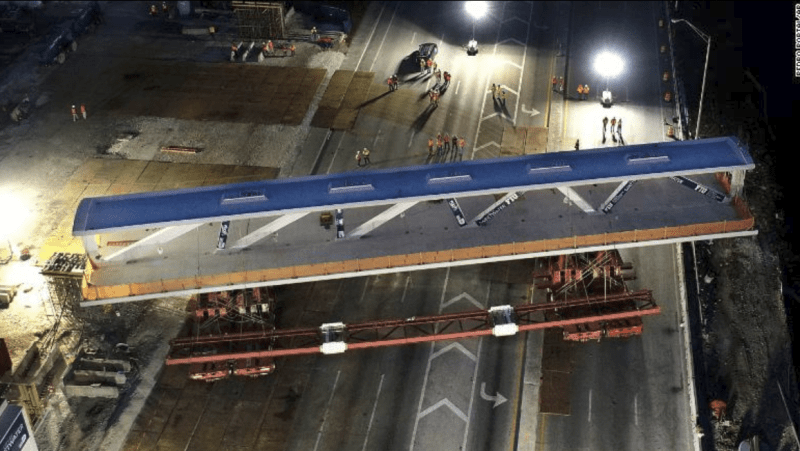
It can be argued that the original scheme may be impractical as some transporter wheels must travel onto the unpaved areas adjacent to the abutments. This will cause unwarranted if not uncontrollable settlements or movements of the wheels and endanger the temporary supports of the bridge.

Comparing the original with the actually executed scheme it would be obvious there had been a design change in the temporary work resulting the two end bays to have the ability to withstand as cantilevers not envisaged in the original design. In the original scheme it would be more difficult to manoeuvre the transporters into position, the rigid linkage between the four transporter supports would have to be more substantial(the original 4 separated supports were in the end bolted together to form just 2 supports), the cost has to be higher (unpaved areas to be concreted over, traffic barriers removed and then reinstated) and the worst of all is the longer construction time.

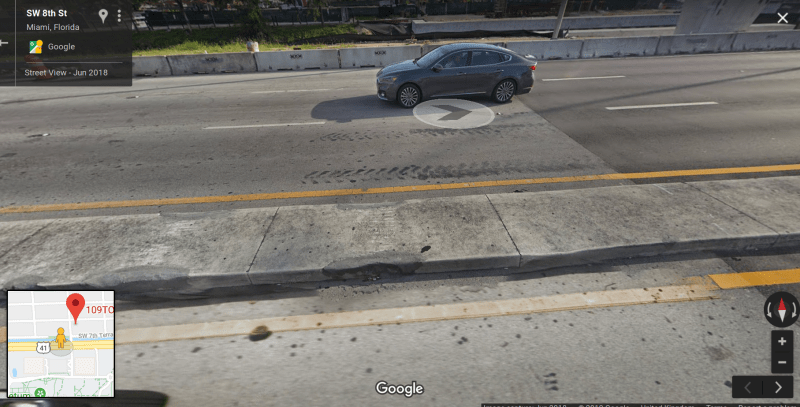
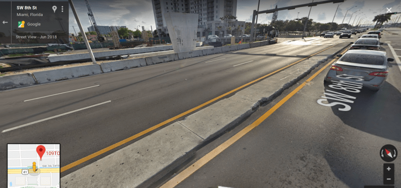
The bottoms of Member 2 and 11 are taper and not intended as support points in the design. Were the two temporary support points structural adequate or suitably strengthened for this purpose? If one looks at the centre divider kerb one may wonder if the design has the dynamic forces considered when the transporters crossed over it.

The Google map does show several newly patched areas at the position where the transporters had to cross over and a long unpatched damaged kerb section possibly sustained during the removal operation of the collapsed bridge.
Screenshot_from_2019-03-29_11-18-15_revz9a.png
Screenshot_from_2019-03-29_11-19-18_psypon.png


It is common in the construction industry for the scheme proposed to win a job to have minor deviations in the final execution. Thus attention to details is the key. The evidence above is just a few need to be considered if the bridge were to be satisfactorily delivered.
 
A while back there was a push to have the design calculations made public. If I remember correctly, they were, however, you had to pay a fee $$ to get a copy. After that I expected to see bits and pieces of those calcs, along with a running commentary, appear in this thread. That hasn't happened. I'm assuming the reason why that hasn't happened is that there is some legal contract that all parties, who receive a copy, must sign that restricts them from making public any info contained within. So a couple of questions:

1) May we expect that after the NTSB releases it's final report this contract will be voided and we will begin to see commentary on the calcs begin to appear in this thread?
2) Or will the calcs be eternally sealed and hidden from the public?
3) In general, calcs are not public documents. So why should we expect them to made public in this case?

The reason I ask is that I would be very disappointed if all we get from the NTSB is a video animation of the collapse, along with a bulleted list of findings, such as insufficient this at node 11-12, or failed to adequately address that at node 11-12. There are a host of other design concerns, not directly related to the collapse, that could've played a role in determining the long term safety of the bridge, some of which are:

1) What was the worst case loading from Creep, Shrinkage, Temperature?
2) Were moments foreseen to develop in the diagonals?
3) How were the diagonals designed?
4) How was node 1-2 designed for DL + LL + (C, S, T)?

I suppose we can't expect the NTSB to redesign the entire bridge. Maybe that's something left to academia. Seeing the calcs would bring out into the open some of these issues. I guess I'm just preparing myself for the release of the report, and being left with a lot of unanswered questions.
>

On a separate note, Were any VSL engineers present during stressing? From my recollection the answer is no. This was a small job with relatively simple PT, so it may have just been the crew working the jacks. My sense is that if VSL engineers were involved--as a separate set of eyes--we'd be having a vastly different conversation today. Or maybe this is just wishful thinking.
 
Green Lama said:
Were any VSL engineers present during stressing?
- No but an inspector from Bolton, Perez & Associates (Engrs) was up on the canopy when it collapsed.
 
Thanks for the note about Bolton. The Miami Herald story mentions the jacking crew as working for Structural Technologies, not VSL. I guess I was mistaken.

Here's a link to a March 26th report about how Bolton and FIGG cannot now agree as to what was said during the trailer meeting minutes before the collapse.
 
The MH story I cited a few spots above said there were at least two ST employees on the canopy. Kevin Hanson, who took cellphone pics of the widened cracks right after after the bridge was moved and forwarded them to higher ups, and Navaro Brown. ST called Hanson back the day before the collapse, and Brown was called away from another job the night before the collapse. Hanson's girlfriend said she was nervous about the cracks and didn't want him to go back the second day. Brown was killed, and Hanson was buried in rubble and ended up brain damaged.
 
Thanks again. I knew I'd seen VSL mentioned somewhere. Hell, I'd even linked earlier in this thread to a PDF technical report, "Detailing for Post-Tensioned," which can be found on the ST link above, however I'd gotten it straight from VSL. I must have just glossed over the Structural Technologies reference and connection.

It's so sad about all who were killed and injured. NTSB identified "design errors" and a construction site timetable are a toxic combination.
 
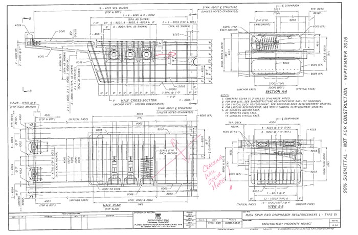
There is a video news story on the NBC Miami page linked above by TheGreenLama. This may have already been discussed in the thread, but in that news video, it is intimated that an FDOT engineer identified the potential failure planes in the concrete as early as 30% review documents prepared by FIGG. The video news story shows still shots of the bridge plans (presumably the 30% review set) with the FDOT engineer's red-line markups indicating where the bridge would crack. It is the same engineer who's voicemail box received the voicemail from the FIGG engineer about the cracks 2 days before the collapse. Pretty telling that the problem was identified so early in the process.
 
On March 14, Tony Pipitone posted a MASSIVE timeline of NBC 6 Miami's investigation of the disaster. The left side is interactive: documents can be scrolled page by page and videos can be played.

EDIT ADD 1: At least in FireFox, if you right-click inside the window and select "This Frame" -> "Open frame in a new tab/window)" the frame will expand to fit your browser window edge-to-edge. In Firefox, you can full-screen the window by using Ctrl-B to close the bookmark sidebar and F11 to eliminate everything else. Reverse with a second Ctrl-B or F11.

EDIT ADD 2: When a document is displayed, click the 4-arrow button at bottom left to open document in a full screen viewer that has an "Original Document (PDF)" link in right sidebar. From there you can print/save the PDF. If you hover over videos and some images, an arrow button appears in upper right corner than can full-sreen the video/image. If no arrow, right-click the image and select "view image".

On March 15 Pipitone posted a news report with a link to the timeline plus several videos. Parts of this post were reused in the March 26 story noted by The Green Llama.
 
Thanks MikeW7 (Electrical)
with your link and hints about firefox, I was able to get a link to the FDOT .pdf file"
30-Plans-Review
Hint: search for "tricky"
 
Wow, thanks MikeW7, that massive timeline put together by NBC6 Miami is a nice summary of events.
 
Thanks MikeW7 for pointing out the NBC 6 Massive timeline which was also mentioned by gte447f

The following may have been covered here and there but I just put them together.
(1) As gte447f said the FDOT engineer has asked many questions about Member 11 specifically on the risk of cracking. The NBC6 timeline indicates on 15 Sept 2016 meeting, or 1.5 years before the collapse, FDOT suggested Member 11 needed to have PT rod to withstand the force when the bridge was lifted. He wrote "Cracking will occur here!" on several drawings. One of them is on the short span a connection similar to Member 11&12 with the deck

Andres_said_cracking_will_occur_here_mlimyh.jpg


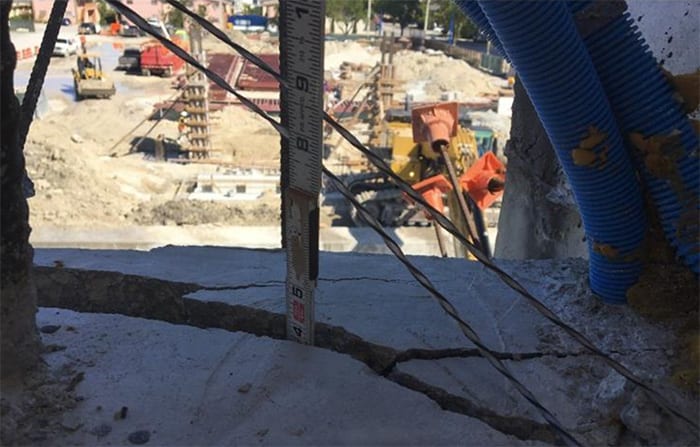
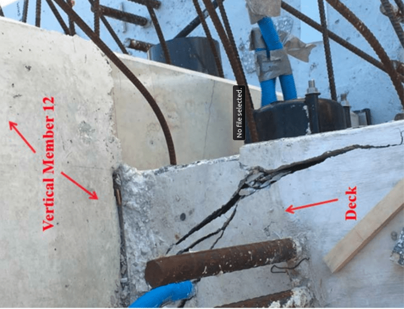
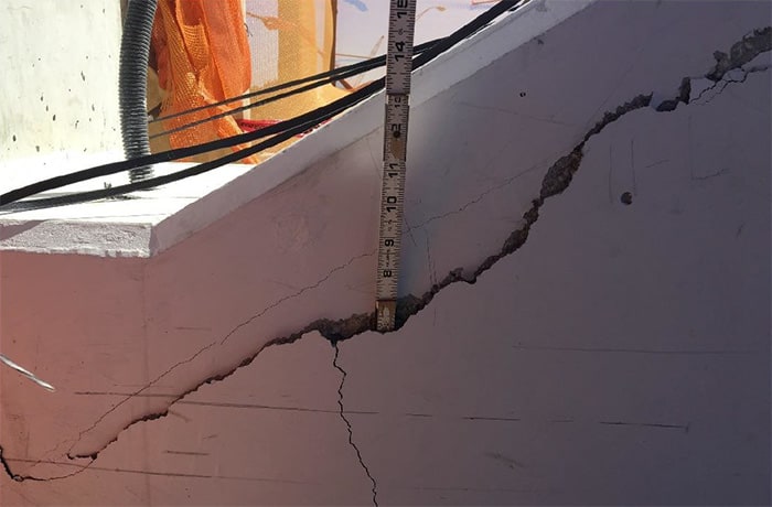
The two photos released by NTSB on 9 Aug update have the similar 45 degree cracks spread out as predicted on both sides of Member 11&12. One photo has been rotated to show the 45 degree crack is almost a mirror image of the other side.

4-INCH-CRACK_mcz2ww.jpg
Screenshot_from_2019-03-30_23-26-51_wlydmh.png


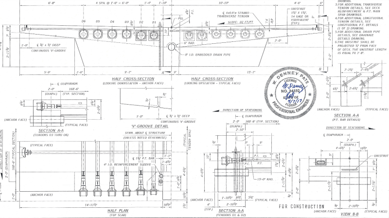
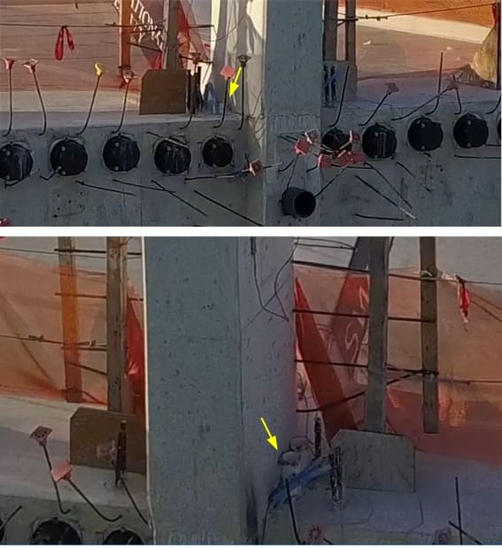
(2) NBC6 has a complete set of the FDOT approved drawings for construction. I post a couple below showing weakness which would be apparent to every reinforced concrete designer. This first depicts the Member 11 having very little concrete continuity vertically with the deck due to the presence of a 8" rainwater pipe.
Screenshot_from_2019-03-30_22-23-06_xhhje8.png


The drawing below depicts on either side of Member 11&12 there were 4 No. of 4" reinforcement tubes and a number of PVC cable ducts. Thus the horizontal continuity of Member 11&12 with the deck will also be compromised. In fact the second NTSB photo shows the crack crosses one of the cable duct.
embedd_items1_lnjiaj.png

The interference of the embedded items can be seen from the photo below which has been posted previously here. Note that the bridge at that time was being hoisted and had not yet dropped onto the support so the severity of the cracks was not yet serious. Member 11 was in tension then.
memer_11_left_back_view_cs2d4t.jpg


(3) Finally in NBC6 the descriptions of the photos taken by the workman, who fell but survived in the accident, alert me the severity of these cracks which I missed out. The first NTSB photo has been described as "4-inch crack" because the tape managed to dip 4" into the crack!

This photo also used by NTSB in the 9 Aug 18 Update and was described as "6-inch crack" because the crack has swallowed a section of the tape of 6" long.
6-INCH-CRACK_mucmup.jpg


Any professional engineer, who had access to these photos showing the most critical structural connection of the bridge has cracked and separated to a depth of 4" to 6", and did nothing to halt the construction or traffic deserves what is coming to him/her.
 
Please discontinue posting in this thread. Go to Part IX thread815-451175 for any further posts.

This topic is broken into multiple threads due to the long length and many images creating longer load times for some. If you are NEW to this discussion, please read the following threads prior to posting to avoid rehashing old discussions.

Part I
thread815-436595

Part II
thread815-436699

Part III
thread815-436802

Part IV
thread815-436924

Part V
thread815-437029

Part VI
thread815-438451

Part VII
thread815-438966

Part VIII
thread815-440072

Part IX
thread815-451175


Check out Eng-Tips Forum's Policies here:
faq731-376
 
Status
Not open for further replies.

Part and Inventory Search

Sponsor