Continue to Site

Eng-Tips is the largest engineering community on the Internet

Intelligent Work Forums for Engineering Professionals

  • Congratulations KootK on being selected by the Eng-Tips community for having the most helpful posts in the forums last week. Way to Go!

Miami Pedestrian Bridge, Part X 50

Status
Not open for further replies.

JAE

Structural
Jun 27, 2000
15,444
A continuation of our discussion of this failure. Best to read the other threads first to avoid rehashing things already discussed.

Part I
thread815-436595

Part II
thread815-436699

Part III
thread815-436802

Part IV
thread815-436924

Part V
thread815-437029

Part VI
thread815-438451

Part VII
thread815-438966

Part VIII
thread815-440072

Part IX
thread815-451175


Check out Eng-Tips Forum's Policies here:
faq731-376
 
Replies continue below

Recommended for you

I'm not sure it's fair to accuse him of destroying evidence just yet.

I agree.

Supposing he was hiding something, what might it be?
 
Sym P. le (Mechanical) 21 Jun 19 21:20 said:
Please, do tell! Who is taking pictures?

I count 3 or 4 people, in the bottom center group, with phones up at the 0:06 mark of the first video

They may just be taking snapshots, but the images could still show cracks. NTSB should have a look at them.
 
Tomfh (Structural) said:
Supposing he was hiding something, what might it be?

The designer has put up a robust stance publicly insisting the cracks were not a safety issue. They might discussed their concerns and worries privately. Such information would undermine the designer's credibility.

I would say if a responsible professional learns a fatal accident has just occurred and his phone contains relevant information the first step would be to preserve the evidence immediately at all cost. Destroying the damaging evidence would be a loyal move to his employer but lacks professional integrity.
 
Dwight Dempsey, P.E., S.E. He was at 3/15/18 meetings via phone, and he is the one who earlier conveyed the message to MCM damage to the structure was not a safety concern.

He is NCEES Model Law Engineer (MLE) What is that?

Important technical document he signed-off on: Read the whole thing, we missed this before.
 
saikee said:
The designer has put up a robust stance publicly insisting the cracks were not a safety issue. They might discussed their concerns and worries privately. Such information would undermine the designer's credibility.

Ok, good point. Possible evidence of a guilty mind....
 
epoxybot (Structural) 21 Jun 19 03:57 mentioned all the political connections that FIU has, but you may be surpised to find out the political connections between the Miami mayor, his police chief, and MCM.

I did a search to see if there was any news about a Miami-Dade police investigation, and came across this article. Some quotes:
[ul]
[li]The morning after the collapse, Juan Perez, director of the Miami-Dade Police Department, said the department’s homicide squad would explore criminal charges for contractors such as MCM.[/li]
[li]Miami-Dade is the only county in Florida where the Mayor picks who runs the police department.[/li]
[li]The Munilla family has deep ties to (Mayor) Gimenez and have been very generous in their political donations, giving thousands to the Mayor and City Commissioners over the years.[/li]
[li]All of this raises the question: If a company with deep ties to the Mayor is under investigation, should his hand-picked police director be in charge?[/li]
[/ul]

This is the only recent news I could find in the Miami Herald:
[ul]
[li]MCM partner Pedro Munilla sat two rows back in the reserved section of Mayor Carlos Gimenez’s State of the County address on Jan. 31. Gimenez’s wife, Lourdes, is related to the Munilla family, and one of the mayor’s sons has lobbied for MCM.[/li]
[/ul]

More from the Miami New Times

Interesting....
 
saikee said:
Has anyone had a view on the collapse based on the historical formation of cracks reported by OSHA?

The re-application of the PT tension did not pull the sections back together because high shear friction, between cracked concrete, would have to be overcome to re-align the moved surfaces.

I generally agree. I'm thinking as follows:

Releasing the PT rods reduces clamp force, reducing shear friction between 11 and the deck, allowing the failure block to start separating (initial cracks widen significantly to become the scary cracks). At this point the PT rods are acting as large dowels. Upper rod is within the failure block and goes with along with it, whilst the lower rod is embedded in the deck, taking huge additional shear load as the crack opens. They tension up the top rod, which worsens the situation since it's pulling the failure block not the deck. The bottom rod is on the verge of shear failure and is hanging on for dear life trying to hold the crack together, and tensioning it up to 85% snaps it, allowing the crack to open freely.
 
saikee119 basically, I agree with you. I just wanted to delve a little deeper into the PT history.
I believe the the PT rods in 2 and 11 were tensioned last, then the shoring was removed. Then the cracks in CRACKS REPORT AFTER SHORING REMOVAL.pdf were photographed. They may be unalarming, but they were noted by the inspecting engineer and are in the same place as the cracks that opened up after detensioning. You postulate that they had been restrained by the PT rods. I agree. I can't determine what initiated these cracks, but I suspect they grew to failure.


SF Charlie
Eng-Tips.com Forum Policies
 
Earth314159 said:
I was thinking the compression would come from the internal hogging moment over the support. My understanding is the C1 and C4 run through the joint. Tr=0.9x48x58.6Kips=2500 Kips. These would also be grouted. The pipe stays would also contribute.
Now that I see how much PT they committed to this tie/continuity I see it could contribute a significant amount of compression at the pylon. I am surprised at the amount, which is about 1800 kips.
Delivering that compression to the deck plane is yet a couple of steps away. The immediate compression force goes into the closure strip at the canopy which has (should have) the capacity to accommodate that compressive load. The closure is detailed on Section A-A, sheet B-57. The casting and stressing sequence intended is Stage 5, sheet B-110. Had they detailed an open joint to allow closing movements at the canopy level we could take that added force as acting at deck level providing the diagonals had the capacity to transfer the forces.
It seems to me that the shortening at the north and south end of the canopy from that added PT force will be the determining factor in how much force is transmitted to the deck. The effective force delivered to the deck level must travel thru the diagonal web members to reach the deck where the push out force from 11 and 14 acts. I think the amount of the force delivered to the deck level will be limited to the amounts that can be delivered when the strains all settle and balance. The effort required in making that analysis exceeds my level of interest , particularly since it will likely never be constructed.
That logic may fly in the face of the concept that the added PT forces creates a negative moment which draws shears to the pylon. Are they alike or must we apply the effects of strain compatibility before we know the amount of moment created over the pylon?
Which brings attention to the phrase "hogging moment" you have used - that is not a term I have encountered before. What is its origin, and where is it a commonly used term? If I can master that I can say I have expanded my engineering knowledge today.
Thank you for the discussion.


Hindsight is 20/20 but I think if I saw the photos of the initial cracks at the base of #11 and #2, I would go back back to double check my shear friction calculations. After the larger cracks opened up, I don't understand how this was not interpreted as a shear friction issue and that it was very serious. I wonder what the other engineers in the project were thinking. Was it like the Korean airliner crash where the co-pilot was too afraid to speak up to the captain? Were the junior engineers concerned about speaking up? We had shear, shear-friction and punching shear hammered into our heads at university.
 
saikee119 (Structural) - I can't say that Bolton, Perez and Associates documentation of the cracks was very good. Maybe there are more photos but close ups don't deliver the overall sense of what is taking place. The earliest cracking locations for member 10 and elsewhere were shown on drawings of the main span trusses. That should have been the case for all the documentation. That said, there is a photo from the 2/28/2018 email by MCM to FIGG that suggests, the cold joint at the base of the 11/12 node was already in the process of delaminating.

Cold_Joint_ccmntj.jpg


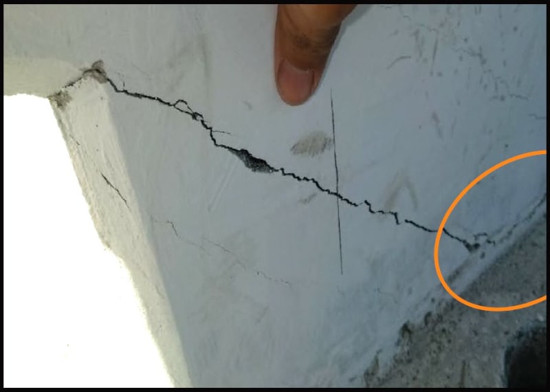
As OSHA pointed out, though painfully obvious, BP&A failed to identify the cracks as structural. The cracks in the back of the diaphragm, migrating from the base of the 11/12 nose, screamed RUPTURE! It is bad enough to see such cracks but when one side of the crack is no longer in plain with the other side of the crack, it is no longer a case of stress relief but a matter of fatigue. The out of plain concrete is actually hiding where the crack has gone in the depths of the concrete. If you are going to probe the depths of a crack, something more slender than a carpenter's ruler might be something an inspector going to examine cracks, might want to carry.

If you include the debonding of the cold joint in with the cracking at the base of the 11/12 node & rupture cracks in the diaphragm; you have one mode of failure. The other is the ?buckling/shearing/flexural-shear? on the number 11 truss. That too is out of plain. This is the crack that should have told Denny Pate he needed to rethink the re-stressing of number 11. I'm curious to know if the cracking in the truss happened after the the 11/12 node/diaphram cracked.

The photo documentation doesn't establish that the cracks were in fact, getting larger. Were they getting wider or were they elongating or both? There are differences in the photos but the difference is simply the absence of small fragments that have either been removed, settled, etc. FIGG's follow up to the presentation minutes, are probably accurate in this regard, that the discussion indicated only minor changes to the size of the cracks.

If you ever have to go out and examine or document cracks in concrete, take a spray both to wet the concrete. A crack can be longer than just what you see or there might be fine brittle failure or tributary cracks to the side of a larger crack. A rough finish can make the extent of cracking difficult to trace. The trace cracks may mean nothing but they may also highlight the fact that the crack has indeed traveled to the element to which you were primarily concern. Example: You specify epoxy injection of 20ft of crack that looks to be traveling towards a corbel but "looks" to peter out 3 feet from the corbel. 5 years later your replacing the corbel because the tiny crack you didn't see allowed water to get at the rebar. A nice blend of 70% Water & 30% Acetone makes for a good crack chasing fluid. The surface water/acetone flashes off quickly, while the water in the crack defines the crack with enough residence time to snap a photo.
 
saikee119 said:
Has anyone had a view on the collapse based on the historical formation of cracks reported by OSHA?

Basically, yes, but it is not a matter of closing ones mind to all that was previously revealed or came after. The cracks just tell the same story in the context of everything else.

In my mind there was only one possibility and that was that 11 had to be taken out, either by rupturing or detaching from the deck/canopy and passing through to the other side (queue the twilight zone). The cracks in and of themselves do not lead us any further and, of course, the question of how these should have been interpreted is now under the auspices of various authorities and judges.

As I understand it, the first cracks were noticed and photographed immediately upon formwork removal and forwarded one or two days later. Next are the "cracked all to hell" photos upon release of PT rods, and then photos on several days leading up to the meeting, concluding with a verbal clarification that the cracks were getting worse every day and the cracks are more severe when seen in person than the photos convey.

The story they tell is rather simple. The structure settled upon formwork removal, then upon placement and PT bar release, assumed its new equilibrium, releasing the balance of the pent up internal stresses. It can be argued that this status could have been foreseen by astute oversight and monitored.

My indignation for what happened next is hard to contain and my thoughts are that OSHA came to the proper conclusion that several entities had a responsibility to exercise proper independent and cautionary oversight. Frankly, I don't see how anyone can conclude that the PT bars in 11 had leverage to contain the node or that a cursory visual inspection of 11 would allow one to believe that it had capacity to donate to the cause. These ideas are just absurd.

Difficult decisions have been made before, see Ocean Tower for one.

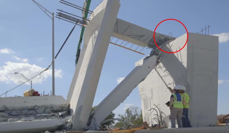
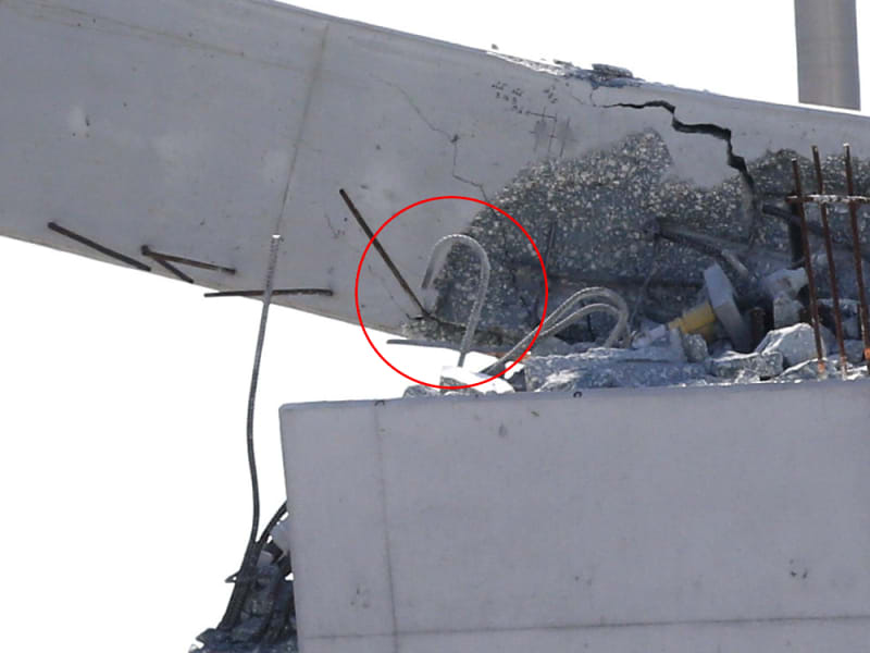
@jrs_87 (Mechanical) and @Tomfh (Structural) - your shear plane and green line drawings are helpful. They follow what I have been thinking but I don't have more to add. I'm not proficient at interpreting the rebar drawings that I've seen to date, maybe shop drawings would help. It would be interesting to identify the exposed rebar in the node and 11. The contortions should also aid in telling the story. I see one hook in 11 that should have followed the lower PT bar and sheared with the cold joint.

CaptureMIAMI_NTSB_luy5b5.hook_r82cfg.jpg


file-20180321-165554-1en0ick.2.hook_vt3ejz.jpg
 
Those J-bars look like the ends of the longitudinal bars of #11. They were embeded in the bottom of #12, They stay with the base of #12 and appear to have not being going through the shear plane (the shear plan dipped down at the base of #12).
 
There are also J-bars with the lower PT rod, which is where I see this one coming from. It's just a question of how close to the plate they were installed.
 
epoxybot (Structural),

On the growth of cracks the photos (Fig 24, 25 & 28 of OSHA) later than March 10 (Fig 23 of OSHA) do show small increase in width, especially in Fig 24 whereas Fig 28 & 29 show part of the delaminated edge broke off completely. There is no doubt that the cracks were worsening and not static.

You mentioned the cracks at the back of the diaphragm of the north end where 11/12 is located. If you examine OSHA's Fig 27 & 25 the cracking pattern agrees remarkably well with OSHA's prediction by Fig 78. The cracks occur along the boundary between concrete compressed inward (deck) and concrete pushed outward (11/12).

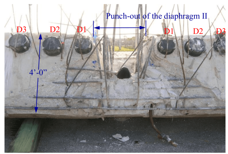
Personally I find it stunning that the cracked concrete of the diaphragm depicted by Fig 27 and 25 debonded totally from the span with little interference with the horizontal rebar after collapse (Fig 62) which shown is below.

Screenshot_from_2019-06-22_01-00-10_g4xni7.png


The bottom two horizontal rebar did not break. The two two rebar were not continuous. The neat detachment makes me think perhaps before the collapse 11/12 might have partially separated from the rest of the structure.


Sym P. le (Mechanical) said:
I don't see how anyone can conclude that the PT bars in 11 had leverage to contain the node or that a cursory visual inspection of 11 would allow one to believe that it had capacity to donate to the cause. These ideas are just absurd.

An experience engineer/designer can quickly identify the weakest point of the structure. The doomed span can be viewed as a glorified Warren truss with a redundant 12 and the canopy attached(same for opposite end). Therefore the critical elements in the system is Member 11 and the deck it links to.

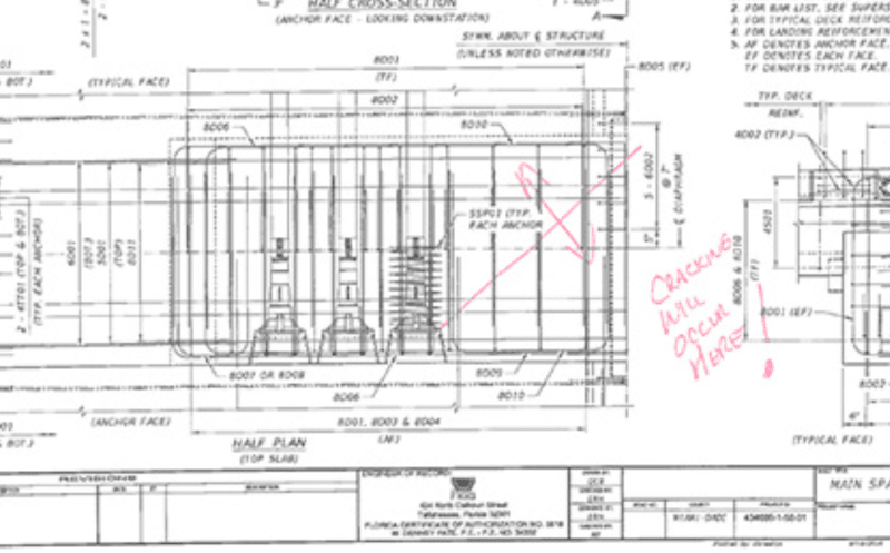
The deck has been post-tensioned (or compressed axially and laterally) throughout except the area occupied by the truss. Under normal load the Member 11 will be in compression pushing the deck section under it outward in the exactly opposite direction to the deck. Therefore any engineer who does analysis would put a magnifying glass to find crack at the interface of 11/12 with the deck as this is the boundary the stress reveres. FDOT engineer when previewing the FIGG drawing also marked up the diagonal crack in RED that could occur at the such location but on the short span. FDOT's marked up drawing is depicted below.

Screenshot_from_2019-06-22_01-31-22_jzgros.png


Therefore if cracks were 1" wide and 4" deep we would expect the engineer responsible unable to sleep at night! I find it absurd to hear professionals insisting the cracks were not a safety issue at such location and severity.
 
Saikee said:
FDOT engineer when previewing the FIGG drawing also marked up the diagonal crack in RED that could occur at the such location but on the short span. FDOT's marked up drawing is depicted below.

Given that FIGG concluded the structure was mistaken to crack there I can’t imagine they’d have be too concerned by someone predicting it would crack there.
 
Sym P. le (Mechanical)21 Jun 19 23:22

Sym P. le said:
shear plane and green line drawings are helpful

Thanks, but my actual goal with green line is to demarcate a cross-section at the center-line for remaining concrete. I do not have shear in mind, but this may be a distinction without a difference. I believe the NTSB or National Bureau of Standards will release similar data collected with advanced scanning and solid modeling.
 
We are on the same plane, I did a sketch of the profile as well but it wasn't worth showing anyone. Have you considered why the slab survived under 11 while everything else blew out?
 
Re: J-BARS
I find it interesting that the concrete around the J-Bars is simply gone. Hit them with a garden hose and use them again. No evidence of stress to the bars.
Where is the concrete? It looks like the concrete blew out like a hand grenade.(Maybe it was terrorists?)
If this is the way 8500 psi Titanium DiOxide concrete works there needs to be a LOT of confinement reinforcing used.
Please comment - I think this is gonna prove critical in this case. Does anyone have experience with concrete and aggregates like this? Is it common in FDOT structures?
Thanks,
 
Vance said:
I find it interesting that the concrete around the J-Bars is simply gone. Hit them with a garden hose and use them again. No evidence of stress to the bars.

Look like it was all broken off during the collapse. It doesn't look like these bars would have been working too hard? They were all above the green line?

Sym said:
Have you considered why the slab survived under 11 while everything else blew out?

The deck PT cables prevented such a failure. The deck couldn't punch out that far back. The crack had to sneak around the cables via the horizontal interface between 11 and the deck, and then it fanned out once it could get around the cables.
 
Status
Not open for further replies.

Part and Inventory Search

Sponsor