Eng-Tips is the largest engineering community on the Internet

Intelligent Work Forums for Engineering Professionals

  • Congratulations waross on being selected by the Tek-Tips community for having the most helpful posts in the forums last week. Way to Go!

Miami Pedestrian Bridge, Part X 50

Status
Not open for further replies.

JAE

Structural
Jun 27, 2000
15,432
0
36
US
A continuation of our discussion of this failure. Best to read the other threads first to avoid rehashing things already discussed.

Part I
thread815-436595

Part II
thread815-436699

Part III
thread815-436802

Part IV
thread815-436924

Part V
thread815-437029

Part VI
thread815-438451

Part VII
thread815-438966

Part VIII
thread815-440072

Part IX
thread815-451175


Check out Eng-Tips Forum's Policies here:
faq731-376
 
Replies continue below

Recommended for you

Vance Wiley said:
I do not visualize the condition this way.
Simply setting the backspan against the main span may let member 11 push against member 14. What holds the ends of the decks together? How do we develop the end thrust of 11 into the pier or allow it to pull on the backspan deck? Nothing is on the drawings that I can find - only misc reinforcing to hold the pour strip over the pylon.
Both spans have expansion joints and slip bearings at their ends so nothing is going to push back from the end supports.
Somehow the diaphragm 2 needs to be clamped to diaphragm 3. As long as there is no diaphragm 3 there is nothing to clamp the mainspan deck to.
I see 1700 kips lifting the 40 strands (16 ea from D1 and 4 ea from D2 adjacent) from their anchorage and stretching them another 2-3/4 inches. I do not see that as effective restraint to node 11/12. And at the point just before collapse I do not see how they could have connected to the 40 PT strands.

The horizontal component of the compression between #11 and #14 is resisted through the CIP pylon. There is concrete at the butt ends of spans in compression. The compression is transferred above the diaphragm level. The difference between the horizontal components is then taken by the shear friction at the pour joint. Since it a difference between the compression forces and the shear friction is spread over two joints, the total shear friction stress is substantially reduced.

BTW, I believe D1 has 12 strands each and not 16. Since the cables are already stretched to 70% and the net force is much less, they wouldn't need to stretch another 2.75". The net force is less than 70% of the D1 PT force. The conduit would also be grouted.

I could be wrong but it looks from the drawings there is cip concrete between #12 and #13 of the two spans. There is a CJ called up next to #13 but it looks like this is just a pour joint.

There is no direct connection to the D1 strands. It is not required if the shear friction is substantially/mostly reduced. I am not saying it is a great idea but it looks like there is some merit to it.
 
I do not think Florida DOT were starry-eyed by FIGG or Denny Pate. They were simply overruled. This project was a Political Gravitas project, with every politician that could legitimately squeeze their name in, doing so. Senator Marco Rubio taught at FIU, Debbie Wasserman-Schultz was involved, along with Governor Rick Scott. FIU is a behemoth. FDOT's Tom Andres was very persistent with FIGG about his shear lag concerns at the 11/12 node.

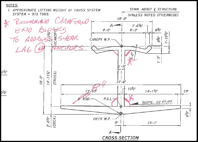
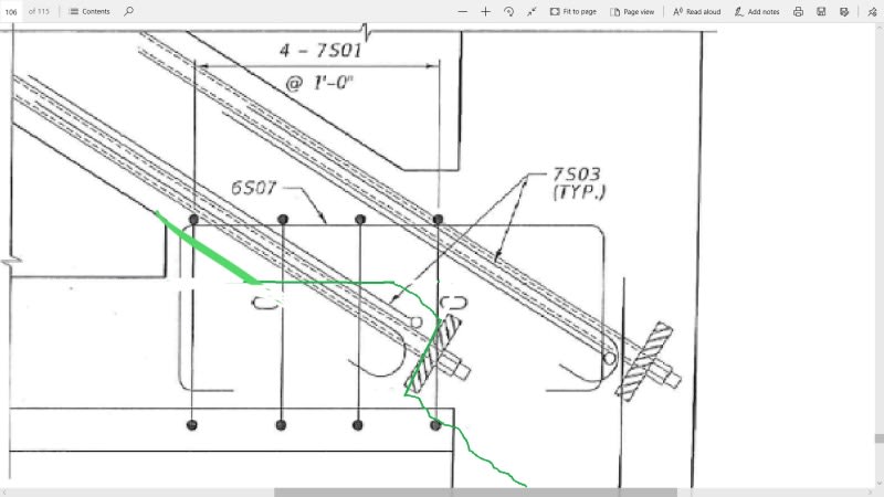
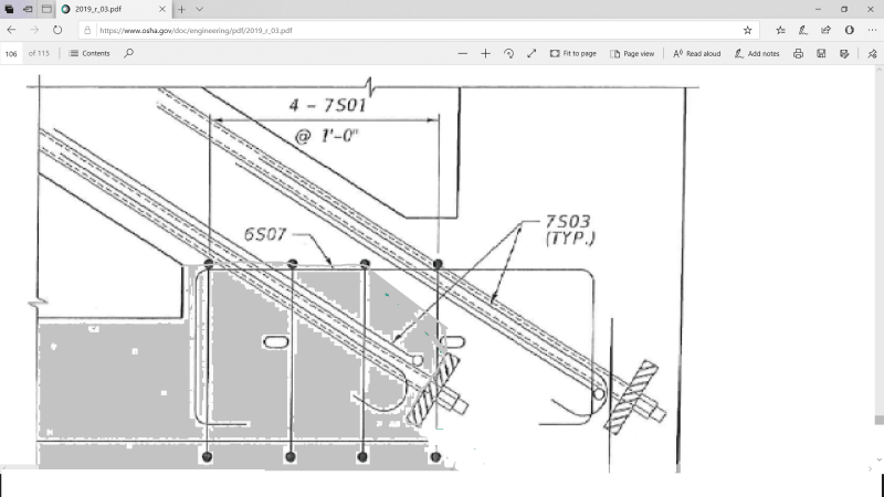
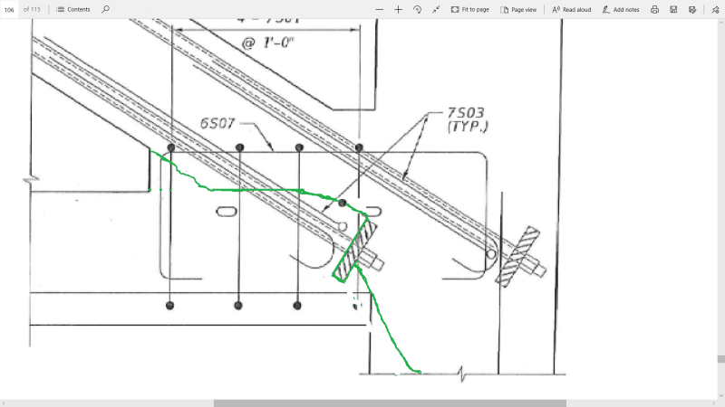
Here is one of Tom Andres last mark ups suggesting extended chamfers around the base of the node. (Ignore the lack of a diaphragm in the drawing. The notes on the drawing were positioned between a congested drawing of the diaphragm & the one shown, which he marked up for convenience.)

Curbs_bzzgcr.jpg


I lived for 10 years, just 1 mile from Santa Clara University, the only supermarket at the time was right across the street from SCU. When SCU decided to expand, the El Camino Real (State Hwy 82) was rerouted at considerable expense. Powerful Alumni & Political connections mean prestigious universities usually get what they want, locally.

FIGG contracted with MCM for design and engineering for a lump sum of $905,000.00. Assuming their portion of the work was the $11.4 million of the total $14M contract, that works out to just under 8%, for Concept, Design & Engineering. The fee was most likely adjusted minimally for additional work with the relocation of the pylon. That doesn't seem to be a lot for what they were proposing. It suggests that FIGG was also in it for Prestige & Political Gravitas. It was they who introduced the ABC method.

Just scanning the MCM-FIGG contract, I didn't see where MCM obliged FIGG to perform a PEER Review as a component of their contract. Yet FIGG, who tried to persuade FDOT to allow another FIGG office to perform the PEER review, finally settle for a PEER review of 90% construction plans. If I recall, they paid Louis Berger about $30,000. FIGG may have been able to kick the PEER Review back to MCM. If they could have, then shame on them for not doing so. Unless, they knew the "Self Supporting" pitch was borderline and wanted to jeep it close to the vest. The MCM-FIGG contract starts on pdf page 326 of the FIU Contracts/MCM .zip file.

EDIT: Louis Berger contract was $61,000 & the MCM-FIGG contract can be found in the NBC FIU Bridge Timeline
EDIT: From BP&A Progress Meeting notes: Design contract was 9.9%
 
Earth314159 compression between #11 and #14 is resisted through the CIP pylon.
Where does this compression come from? If the mainspan is supposed to be a stand alone structure and was simply set on the pylon, it can have no free forces to create external compression. The compression of 11 is supposed to be resisted internally, but has failed. The backspan is cast in place so the wet concrete will not create free forces. Removing falsework would load 14 in compression but in my mind intelligent design would have that force resisted internally also. When the thing fails, of course you reach for anything.
Since node 11/12 was failing, how much capacity is left? (Assuming you get there before it colllapses).
Anything relied on would have been an assumption. FIGG advanced an idea to restrain (capture) 11/12 with channels extending to 9/10 at the deck level. We will never know if they intended those tiebacks to be temporary. Then they said the backspan would do the job so it appears they intended the ties to be temporary.
Here is a previous post:
Vance Wiley (Structural)18 Jun 19 18:27
Quote:
saikee119 (Structural)18 Jun 19 17:23 quoting "The fact the bridge collapsed before FIGG’s strengthening scheme could be devised is a good testimony on the technical competency of FIGG on the matter."

"Being sarcastic, right?
I still question this statement/position by FIGG: "Such restraint would of course be provided by the erection of the side span had the bridge been able to achieve completion. "
Could someone identify the elements/parts in the closure strip over the Pylon which will provide 2000 kips of tension tie between the north and main {deck ?}."

 
Vance said:
We will never know if they intended those tiebacks to be temporary. Then they said the backspan would do the job so it appears they intended the ties to be temporary.

From the pre-collapse meeting minutes:

CEI to FIGG: Do we need temporary shoring? o FIGG responded that it was not necessary. Rather than carry weight, carry load off that number/node. Steel channels to 10/9 node & PT Bars to capture some of that force which is better than vertical support. The diagonal member is what needs to be captured • FIGG mentioned that no repairs should be done now. Once back span is there, member 11 force will decrease, then repair can begin. FIGG also stated that the prudent action is to share the load carried to 9/10 and construct pylon diaphragm

CEI to FIGG: Will the mechanism to capture the load from the node have to be integrated with the pylon diaphragm and will it remain in the structure? o FIGG answered that the temporary mechanism to capture the node, preferably will not remain in the structure


It does sound like they were hoping to tie it all together at the pylon and then remove the temporary 10/9 ties?
 
epoxybot, not to diminish the contributions of others, I don't know what this thread would be like without you. Thanks.

Do you think to chamfers were not considered due to the complexity of formwork required?

I'm from the Bay Area as well. I rode in BART before is was open to the public. I visited Ames Research Center about six years before the space shuttle was first launched. The tour guide admitted the tiles would likely lead to loss of life, but no alternative exists. My point being back then things kind of got done. Now, well, they blow it on high speed rail. I just hope California does not ever have a St. Francis Dam type disaster again.
 
Please improve crude green line in first image or point to previous better one. I can see line needs improvement, need help or more time. The steel rule may provide scale. This is an interesting profile to me that I have not seen before. My goal is to see a crosshatch of all remaining concrete. Also in the drawing where is the rebar shown in photo 2, 3, 4? And what is it's function?

0_crumil.png
1_a6gewi.png
2_kyhnlw.png
3_gpetyq.png
 
Jrs said:
.Please improve crude green line in first image or point to previous better one

Quick adjustment:

The triangular wedge was there at moment of failure, although may have been subsequently shaved off during collapse.

I also think the green line should cross through the PT anchor plate, not run below it. The PT anchor appears to have dug in, hence it remaining in the deck.

4C69F9A2-43A2-43DA-910D-18C502F014D3_mcfggl.jpg
 
epoxybot (Structural),

I also note that the FDOT engineer has marked up many drawings to convey his concerns including the locations of diagonal cracks now appeared remarkably similar in the doomed structure.

The information from FDOT is truly outstanding. I have the highest admiration of his in depth foresight of the problematic areas of the bridge and regard his contribution to the bridge as exemplary from his official position. I just hope his effort will not be misused by the legal people as excuse for contributing the collapse.

The one I got in mind is the suggestion to have the PT bars inside Member 11 which does not have any in the original design.

9-15-16_Andres_Note_on_Member_11_pu5bxi.png


The tensioning, de-tensioning and then re-tensioning of the PT bars in Member 11 can be a hot subject for debating the root cause of the cracks.

Technically we all know the design of this doomed span in its final position is simply supported by 11/12 at the north end. During the SPMT hauling the bridge was supported near 9/10. Thus it is necessary to strengthen Member 11 which reverses the stress to become a cantilever during hauling.

FIGG did not have to follow FDOT suggestion and could have strengthened Member 11 with a different scheme of its own. How much the legal people would use FDOT's good will to evade FIGG's accountability remains to be seen. I am sure they will a have a go at it.
 
Tomfh (Structural)21 Jun 19 11:08
Thanks.

Anyone care to help refine this? I have not yet reconciled deck level with PT bar and rebar position.

00_x8ms6z.png

or
0000_hweai1.png
 
How can it be a year later and yet there has been so little effort put into collecting Pates phone? I would have thought that the NTSB would have subpoenaed it as part of the evidence gathering procedure shortly after the failure. Did the NTSB just rely on the good will of those involved to turn over all their records/evidence?

It certainly makes me wonder what other evidence is "lost".

There must have been some quite damning evidence on that phone. Sadly, there will likely be no repercussions from his destruction of evidence.

As for the "capturing" of member 11. I'm not a structural person, but my first thought when reading the morning meeting notes was that expecting anything other than the deck of that truss structure to hold member 11 in place is a complete fantasy. That span has to be capable of properly working by itself, no ifs, ands or buts about it. Any discussion about how that capturing might have occured is academic at best.

There were comments about doing repairs in the future. In my mind, the only way to properly repair would involve breaking up a large portion of the end of the structure and re-pouring. This assumes it is even possible to re-pour part of the deck. It also makes me think this bridge would be very difficult to maintain during it's expected life span.
 
saikee119 (Structural) 21 Jun 19 11:37 said:
The information from FDOT is truly outstanding. I have the highest admiration of his in depth foresight of the problematic areas of the bridge and regard his contribution to the bridge as exemplary from his official position. I just hope his effort will not be misused by the legal people as excuse for contributing the collapse.

Tom Andres was a seer. I wonder if he'd already outlined the details for what would become the FDOT Preliminary Fact Sheet (bolding was present in the original):
This pedestrian walkway was built at an off-site location by MCM and moved into place on March 10th. The walkway was set in place on top of two piers which were constructed on-site. Again, this is not an FDOT project. FDOT’s role is to administer funding and perform a preliminary review for general compliance with the agreement between FIU and the state. FIU’s design build team is responsible for the proper and safe completion of this project and for compliance with all applicable laws and engineering and construction standards. Additionally, any testing done to the structure following its installation was the responsibility of the FIU design build team.

I hope Andres isn't going to be tormented the rest of his life, like Roger Boisjoly.
 
LionelHutz said:
Sadly, there will likely be no repercussions from his destruction of evidence.
I'm not sure it's fair to accuse him of destroying evidence just yet. My wife has washed my pants with my wallet and keys in the pockets more than once. Fortunately we parted ways before cell phones came along or I would have lost some of those to the washer too.
I find it surprising that OSHA, FDOT, or some other agency did not immediately impound the phones of everyone involved just to prevent such a predicament. Maybe they did and we are just now hearing of the washing machine incident.
On a related note though, if text messages do not live on in the servers of the cell phone service providers, they will still exist on the other points of origin or recipients phones, and I would think that there would be some record at least to indicate to whom he sent/received messages to/from and when. I routinely go through my old messages and delete them though, as my phone gets cluttered otherwise. Maybe all of that data is not really lost forever, just requiring more work to find it.

Brad Waybright

It's all okay as long as it's okay.
 
thebard3(Computer) 21 Jun 19 14:17 said:
I find it surprising that OSHA, FDOT, or some other agency did not immediately impound the phones of everyone involved

I can't find an update to this story, but the pictures taken by Kevin Hanson immediately after the de-tensioning on 2018-03-10 have never been released because possession of his phone is tied up in a court battle. Hanson was left brain damaged in the collapse and doesn't have a say in the matter.
 
LionelHutz,

Does the NTSB have subpoena power? I think they would have to get the DOJ involved and get a warrant.

EDIT: Per jrs (below), the chairman does have subpoena power.

Ultimately, it's a terrible look for Mr. Pate. Everyone else is handing over everything (to our knowledge).
 
Spoliation, destruction or loss of evidence

Parties to the investigation may decline to participate as parties to the hearing, but may still be compelled to provide witnesses or records via subpoena or otherwise. 49 U.S.C. § 1113(a).
 
LionelHutz (Electrical),

Officially the key evidence is already in the public domain as the voicemail by Denney Pates saying the cracks not a safety concern is available in Youtube


Normally if there is nothing to hide the phone owner would immediately secure the phone in a safe place, to preserve the information as evidence and use another phone. The fact this phone was conveniently sent to a washing machine tells us something about the owner who could choose to provide all the recipients' names so that any relevant information could be recovered from the receiver side.

The key evidence is the photos taken by the workman who inserted a tape into the cracks to document their depths. Without the photos the guilty party may never be found.

To me it isn't a fantasy to capture 11/12 with the assistance from 9/10. The failure was caused by inadequate resistance in the structure to restrain 11/12 from moving outward to the North. A couple of PT rods with anchors blocks at 11/12 and 9/10 could halt the movement immediately and buy time for the designer to engineer a permanent solution.

I would venture to say the entire strengthening installation could be done in half a day as it just amounts to cutting and welding some heavy structural sections to form two end anchor blocks and use large threaded rods to tie the two steel blocks together, one at 9/10 and one at 11/12. The problem is the designer did not share this urgency.

The designer's failure, as listed as the first key investigation result by the OSHA report, is "failed to recognize that the bridge was in danger of collapsing when it inspected it hours before the collapse".

The seriousness of the cracking problem was already known on March 10 2018 and described "it cracked like hell" by the workmen who first released the PT rod tension in Member 11. More workmen, even not as professionally qualified as the designer, felt concerned and took more photos afterward showing the cracks were growing. Only the designer did not know the bridge was in imminent collapse. He offered to come back on March 17 2018 with a strengthening scheme (to capture the runaway 11/12).
 
Status
Not open for further replies.
Back
Top