Continue to Site

Eng-Tips is the largest engineering community on the Internet

Intelligent Work Forums for Engineering Professionals

  • Congratulations GregLocock on being selected by the Eng-Tips community for having the most helpful posts in the forums last week. Way to Go!

Miami Pedestrian Bridge, Part X 50

Status
Not open for further replies.

JAE

Structural
Jun 27, 2000
15,463
A continuation of our discussion of this failure. Best to read the other threads first to avoid rehashing things already discussed.

Part I
thread815-436595

Part II
thread815-436699

Part III
thread815-436802

Part IV
thread815-436924

Part V
thread815-437029

Part VI
thread815-438451

Part VII
thread815-438966

Part VIII
thread815-440072

Part IX
thread815-451175


Check out Eng-Tips Forum's Policies here:
faq731-376
 
Replies continue below

Recommended for you

jrs_87 said:
Quote is not from me.
My sincere apologies. I see now that it was a reply to you by another person.
I have corrected the post. (I think) - I certainly intended to do so).
Thank you.
 
saikee said:
I think we can agree that in tension zone the rebar need to be gripped by the concrete to develop the full material stress in steel. I am not sure such adhesion between concrete and steel can be classified as the concrete tension.

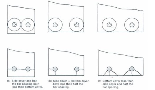
It is tension. So called "adhesion" between the concrete and the bar depends fundamentally on concrete in tension. That is why concrete splits when a bar anchorage fails.
TENSION_uwy37s.jpg


It's why you increase the anchorage length - to dilute the concrete tension to below acceptable limits.

"Adhesion" and concrete in tension are one and the same. Draw a Mohr's circle and you will see. The pure shear force has a corresponding tensile component. There's no way around it.

Likewise a concrete element in shear (e.g. a slab) has internal tensile forces which carry the load. They are there. Real tensile stresses/strains which carry your load back to the supports.

Don't kid yourself - you rely on concrete in tension all the time.


This bridge is what happens when you over rely on it.
 
Vance Wiley (Structural)20 Jun 19 23:10

You are correct about backspan not supporting main span. I think most references to this idea on forum are rhetorical, not to be taken literally. Disclaimer: I'm not civil engineer> I find the pylon design to be full of mysteries. It's on low friction pads, but it's bolted down (I don't know how to look of isolation). Was it to be grouted and thus the stair case landings slide? The bearing on south size pier does not look low friction to me. Perhaps it has horizontal freedom to distort?

If the main span and main span contact in this design it has to be tight to prevent spalling. What is the purpose of the key on diaphragm II? The canopy has no such key.

After looking at other structure lift videos, I have come to the conclusion this project was unworkable with the given budget and limited onsite talent. It required more money, contemplation, and EOR needed to live near by. It was treated like a red-head step child.

Amusing diversion:
Millennials have another problem:
 
jrs_87 said:
It is suspect that they compromised the north end in size to fit the pylon and backspan on the landing.

The revised TY Lin Design Criteria (Rev 1: revised location of northern tower) were published April 2015 and the MCM-FIGG Proposal was dated September 2015, so it would appear FIGG didn't need to make any corrections for the Pylon move.

Perhaps this has already been addressed, but what if all of FIGG's simulations (and faulty assumptions) were based on a completed bridge. What if they never simulated the highway span by itself? Probably a wrong assumption, because they would have had to simulate the stresses anticipated during the move. Correct?
 
Let me be the first to complain: The functionally of this website has not scaled well to this super long thread. I'm sure we all are finding it tedious to use. Crossed-messages and misquotes are bound to happen. Many of my posts have gone poof while composing. (For me, that's a feature not a bug).
 
vance willey said:
The stairwell is intentionally separated from the bridge by an expansion joint. The South end and North end are resting on slick low friction bearing pads to allow expansion and contraction. Both spans are anchored to the pylon beside the canal to stabilize the entire structure.
Member 2 and member 11 simply had to perform their task (if you will) without failure for this truss to work and be safe.
No provisions were apparent in the drawings I have seen on this forum which could have anchored or restrained the 2000 kips of factored horizontal force that would develop at node 11/12 and the deck. To say the back span would have stopped this is defensive rhetoric without basis. It is a fantasy wish and if that is all there is to grasp onto to save ones career, that career is already gone.
If I recall correctly, the total PT force longitudinally in the deck was about 2600 kips. The northward thrust of 11 at the deck surface was about 2000 kips factored TL. They would have to connect about 80% of the longit PT strands of the main span to the back span to restrain (or capture) node 11/12. Capture is actually a good word in this case - perhaps slightly Freudian in nature, because the node 11/12 had actually "escaped".

This is my first post on this forum, so I hope I am following protocol. The horizontal component, once it is factored up, should be around 2000 Kips. I calculate a factored load of a bit less than 2000 Kips for the simply supported truss (without the back span) but the hogging moment with the back span will increase the force on the diagonal. The factored resistance of the cables is around about 11000 Kips. The cable capacity is not an issue for the diagonal. In fact, the truss at stage 3 only needs about 1700 Kips factored so you only need all the D1 cables and 4 cables from D2 on each side to safely resist the diagonal force.

The shear in the horizontal plan is reduced by the back span which is why they are saying the back span helps for the final stage. The two diagonals (#11 and #14) push against one another which reduces the shear load through the pour joint. The deck member force would be in compression with the back span, so you would need 0 kips from the PT at this section. For the full gravity load case, no PT cables would have to run through the joint.

However, the stresses through the shear plans at the other joints are still very high. You solve one problem with the argument of #14 and #11 pushing against each other but you haven't solved all the problems. Even if you ignore the stage 3 disaster, there are issues with the design. I think those issues could have been designed out but they weren't.
 
MikeW7 said:
What if they never simulated the highway span by itself?
(Electrical)20 Jun 19 23:58

Dollars to doughnuts they did not. Also, since when can concrete be overloaded curing construction as long as it's just for short time? Case in point, what if 11 had to be distressed proportionally and simultaneously while diaphragm was loaded at end of move?

Everyone should be sure they did not miss this post: epoxybot (Structural)20 Jun 19 05:19)


Earth3141 said:
The shear in the horizontal plan is reduced by the back span which is why they are saying the back span helps for the final stage.

I thought we were saying there is no back span? It's just separate simple spans?
 
Any idea the there is no backspan is negated by the fact rebar is poking out all over the place on diaphragm II.
 
jrs_87 But the highway span was supposed to sit in isolation for a long time (months?) while the canal span was built, the pylon was erected, and the faux-cables installed. During that time summer storms would be expected, including torrential downpours and major wind events like microbursts, etc. Hurricane-force winds could strike it from due east or west, and turn it into a concrete "Galloping Gertie" without its magic faux-cables, or worse, just blow it off its slippery pier pads (wild assumption).

Would MCM-FIGG really install such a structure over an active highway with no real expectation of what could happen to it during a multi-month period? Perhaps the more important question would be, why would a building authority (FDOT?) even allow it. ABC is supposed to allow a complete (or nearly complete) structure to be moved into place in a day or two. How in the heck did nobody think twice about allowing someone to install just half a structure, a structure that needed to be whole to be strong and safe. Something for the code boys to think about...
 
Tomfh said:
I thought we were saying there is no back span? It's just separate simple spans?
I am just jumping in for the first time here and most of my analysis was of stage 3. It looks like C1 and C4 run through to give partial fixity at the centre/pylon support. It would not be continuous like a double span beam but you can adjust with the design moment with tension from C1 and C4. This is or course ignoring any redundancy from the pipe stays.

Either way, the concept is the same for reducing shear with #11 and #14 pushing against each out.
 

Tomfh (Structural),


We should not have to argue something fundamental and published in the design reinforced concrete code. The one below is from ACI 318. This has never been changed between various national codes and is applicable in both elastic to limit state designs.

Screenshot_from_2019-06-21_01-28-11_o37l0s.png
 
jrs-87 said:
But the highway span was supposed to sit in isolation for a long time (months?) while the canal span was built, the pylon was erected, and the faux-cables installed. During that time summer storms would be expected, including torrential downpours and major wind events like microbursts, etc. Hurricane-force winds could strike it from due east or west, and turn it into a concrete "Galloping Gertie" without its magic faux-cables, or worse, just blow it off its slippery pier pads.

Would FIGG really install such a structure over an active highway with no real expectation of what could happen to it during a multi-month period? Perhaps the more important question would, why would a building authority (FDOT?) even allow it. ABC is supposed to allow a complete (or nearly complete) structure to be moved into place in a day or two. How in the heck did nobody think twice about allowing someone to install just half a structure, a structure that needed to be whole to be strong and safe. Something for the code boys to think about...

This is an issue with all kinds of structures under construction. There was a building collapse on to Younge street in Toronto during the construction process. There was nothing wrong with the final design. The contractor has control over the site and in most projects it isn't realistic for the engineer of record to track each stage. However, I think you are correct, a large PT bridge like this should be designed for appropriate forces during the construction process. It is normal/necessary to design PT for multiple stages. The project specs didn't require this but did note they wanted (not required) intermediate stages to be designed to code levels. There are some momentary stages that can't meet code which is probably why the spec doesn't make it a requirement. Having said that, IMO, any large heavy element hanging over the public should be designed to code regardless if it is temporary or not.
 
MikeW7 (Electrical)21 Jun 19 00:38 said:
(FDOT?) even allow it.

They were mesmerized by the edifice they were helping create. That's why.

Edit: Strike above out. Eloquently corrected by epoxybot (Structural)21 Jun 19 03:57.


saikee said:
We should not have to argue something fundamental and published in the design reinforced concrete code.

Yes, you must ignore concrete tensile forces passing thru a flexural or axial cross section. In those cases you cannot rely on tensile forces perpendicular to the potential failure plane to resist the flexural or axial load.

I'm referring to all the other tensile forces we rely upon. Concrete tension as a result of shear load. Concrete tension when developing stress in a bar. Concrete tension when relying on shear friction (which may end up breaking out of the back of your bridge deck if you're not careful). Etc.
 
We need Whoopi Goldberg to step in and diffuse the TENSION in this thread please.
 
jrs_87 said:
They were mesmerized by the edifice they were helping create. That's why.

Well, I did mention in previous posts that I thought FIGG, Figg and Pate were rock gods (17 Jun 19 14:00), and Pate was a demigod (18 Jun 19 15:09).
 
Earth314159 said:
The shear in the horizontal plan is reduced by the back span which is why they are saying the back span helps for the final stage. The two diagonals (#11 and #14) push against one another which reduces the shear load through the pour joint. The deck member force would be in compression with the back span, so you would need 0 kips from the PT at this section. For the full gravity load case, no PT cables would have to run through the joint.
I do not visualize the condition this way.
Simply setting the backspan against the main span may let member 11 push against member 14. What holds the ends of the decks together? How do we develop the end thrust of 11 into the pier or allow it to pull on the backspan deck? Nothing is on the drawings that I can find - only misc reinforcing to hold the pour strip over the pylon.
Both spans have expansion joints and slip bearings at their ends so nothing is going to push back from the end supports.
Somehow the diaphragm 2 needs to be clamped to diaphragm 3. As long as there is no diaphragm 3 there is nothing to clamp the mainspan deck to.
I see 1700 kips lifting the 40 strands (16 ea from D1 and 4 ea from D2 adjacent) from their anchorage and stretching them another 2-3/4 inches. I do not see that as effective restraint to node 11/12. And at the point just before collapse I do not see how they could have connected to the 40 PT strands.


Re discussion of concrete tension -
Where does VQ/IB fit in this discussion?
 
Status
Not open for further replies.

Part and Inventory Search

Sponsor