Continue to Site

Eng-Tips is the largest engineering community on the Internet

Intelligent Work Forums for Engineering Professionals

  • Congratulations KootK on being selected by the Eng-Tips community for having the most helpful posts in the forums last week. Way to Go!

Miami Pedestrian Bridge, Part X 50

Status
Not open for further replies.

JAE

Structural
Jun 27, 2000
15,444
A continuation of our discussion of this failure. Best to read the other threads first to avoid rehashing things already discussed.

Part I
thread815-436595

Part II
thread815-436699

Part III
thread815-436802

Part IV
thread815-436924

Part V
thread815-437029

Part VI
thread815-438451

Part VII
thread815-438966

Part VIII
thread815-440072

Part IX
thread815-451175


Check out Eng-Tips Forum's Policies here:
faq731-376
 
Replies continue below

Recommended for you

jrs_87 (Mechanical) said:
It this the correct book to study in regards to this accident?

I think it takes a reinforced concrete designer to understand/appreciate the accident.

A lot of the information is from studying the construction drawings to figure out what the designer was up to.

From your background as a mechanical guy I would venture to say reinforced concrete is different to metal, say carbon steel, in that it is inhomogeneous. By which I mean if you apply compression to a reinforced concrete section both the concrete and steel share the load. However in tension concrete is assumed to take no tension (except in prestressing where a very small amount may be considered especially when both concrete and steel are within the elastic stress range).

The failed bridge did not fail by pure tension or compression but 11/12 sheared off from the deck. Concrete alone can resist shear but the capacity can vary with the amount of rebar present in the concrete. On top of this rebar can be installed to resist shear just like carbon steel does.

Reading a book or several of them isn't going to be enough to understand the root cause of the failure. For example there are secondary considerations like the ability to develop the full steel stress when it is embedded in concrete. At the point you need the rebar to give its full material stress you have to embed either end to a sufficient depth called the development length, otherwise the rebar will not be able to play its full role as seen in the failed bridge. So apart from the stress calculation a reinforced concrete designer has to know how to arrange the steel reinforcement to achieve the intended results. The second part is normally the skill from the reinforcement detailer preparing the rebar drawings.
 
Hi MikeW7, I was referring to Trey as being Auburn graduate, not the host of the video channel. This is Trey.
2019-06-19_4_lw5mrf.png

Anyway, I'm very happy to be in a pig sty.
 
jrs_87 - I think my brain slipped out of gear for awhile..... That was a great video. I don't know how Destin manages school, family and a fantastic YouTube channel all at once.
 
saikee said:
However in tension concrete is assumed to take no tension

Only problem is that it's not true. We engineers are clearly very embarrassed about loading concrete in tension. We even have funny euphemisms like "concrete contribution to shear capacity" and "stress development" to describe when we're doing it.
 
I'm going to say something to see what happens to me: "cement truck"
 
So help me. guys ('n gals).
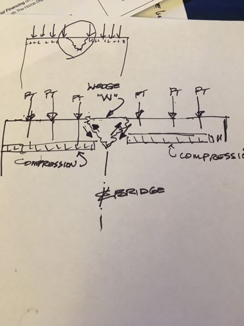
It seems to me that unstressed zones across the end of the deck create a bit of a problem. For instance, the "wedge" W in the sketch is not compressed but the adjacent concrete, particularly near the spirally reinforced anchors of the PT, is in compression. It seems there should be a transfer of shear across the sides of the wedge, where I have shown the little arrows.
FIU_Shear_in_wedge_xwnoq7.jpg

This shear would be additive to any loads on the top of the wedge wedge which try to push the wedge out the end of the deck, right?
Are those shear forces from the "shear lag" of the PT forces enough to require consideration in the design?
Did they contribute to this failure? Can anyone do an FE analysis to evaluate this? It may not be significant, but I think it exists.
There is also a top-to-bottom shear lag present because the PT is near the top and the deck is 2 feet thick. That could add to the shear somewhere in the xone between the PT rods in member 11.

Thanks,
Vance
 
Concrete is NOT weak or negligible in tension. Sand is. (My engineer hat is off) I don't really mean that, but I have always found then term "concrete is strong in compression and weak in tension" to be an extreme over-simplification. I even ponder the term "reinforced", but I'm a nerd. My dad said you can build anything with un-reinforced concrete that you can with reinforced - it's just the resulting structure would not be as efficient and it may be unwieldy. Sorry to go out to left field again. Anyway my father was civil engineer and I admire the skills you structural guys have. I ended up in CNC machine tools, not as demanding (but still replete with pitfalls). Watch out, CNC 3D printed structures are the future.
 
Vance said:
It seems there should be a transfer of shear across the sides of the wedge, where I have shown the little arrows.

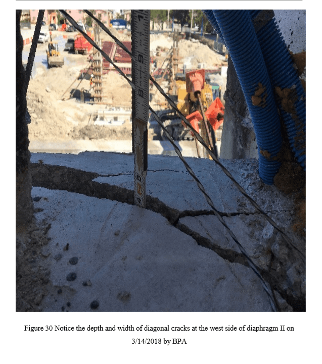
NO! That wedge/cone had punched out and was an inch wide crack! It's the failure itself. It's where the concrete has let go of itself. See here:

wedge_crack_pfdr4s.png
 
There is certainly no transfer after the crack is an inch wide. I was referring to a stress induced by the less than uniform compression created by the PT forces only and before any loads were placed on the structure. I was curious about the intensity of the pre-failure shear stress and I do not have a method to determine that stress. If it is anything significant the demand for reinforcing would be even greater.
What is interesting about that photo is the tape seems to be inserted right over the PT "D1" location - about 8-1/2 inches from the face of 12. The deck must have been delaminating at that time because the PT anchorage appears intact in OSHA photo 61-62-63 series.
Also the final outcome was already determined when that photo was taken.


Vance said:
I was curious about the intensity of the pre-failure shear stress

Ahh, sorry.

With everyone (particularly FIGG) adding up shear capacities AFTER the deadly cracking had occurred I mistakenly assumed you were doing the same thing.

As for the shear strength along your 45 degree wedge, you could calculated it if you wanted. It will be a be slightly stronger than the flatter wedge that actually developed. The PT clamping force isn't really doing much for you though in terms of holding the wedge in. The crack went straight around the PT.
 
All is cool. Communicating this way is great but easily mis-interpreted. And I am far from good at typing and precise descriptions.
I am thinking about a condition like standing on a foam mattress with your feet maybe 18" apart. The foam will not be flat between your ankles - it will billow upward relative to the bottom of your feet. It will be lower than it was before you stood on the mattress, so there is some force pulling it down - trying to compress the unstressed part. That is not a particularly good analogy because there is relatively good tension available in the surface of the mattress which will help compress the 'billowing' zone, and the force is not only shear. Maybe a mattress with individual pocketed coils is a better example. I think we had one of those sometime in the years past.
The answer hides behind the elasticity in compression and shear, the dimensions, and the loads applied. I am too old to even start such an analysis.
 
Vance said:
The answer hides behind the elasticity in compression and shear, the dimensions, and the loads applied. I am too old to even start such an analysis.

I would like to see the result of such an experiment. Eg your sketch, pull the wedge out with the PT load on, and then repeat with the PT load off. Compare the results. How would that PT force affect the wedge failure? Would you get more "shear force" developing like in your sketch?

It's related to another topic of debate we have in our office regarding what the force does at a PT live end. How does it enter the concrete?, and at what angle?, and what sort of stress patterns develop in the concrete?

 
This has probably already been discussed but here goes. When members 2 & 11 were stressed, the entire bridge was still supported by shoring. Jan 13 - 30. Shoring was removed February 23 to 24. This is when loud popping sounds were heard and cracks were found at the base of 2 & 11.

FDOT's Tom Andres had always been concerned about cracking in 2 & 11 from shear lag during the tensioning of the deck, canopy & truss members. FIGG assured FDOT that the stressing sequence had been checked with FE modeling. Under what loading conditions? Did the full bridge shoring during tensioning of 2 & 11 camouflage the shear lag problem? Since the final disposition of the span was to have 2 & 11 PT Bars detensioned, shouldn't they have been tensioned when supported only by the diaphragms? When 2 & 11 were released, did this induce a greater degree of shear lag/thrust? I'm beginning to wonder if Denny Pate didn't realize this and thought that by retensioning 11, he could recapture the shear lag set free when 11 was detensioned. It would kind of explain Pate's state of mind, believing he could fix it.

I have been trying to determine how much the 11/12 node moved horizontally and finally decided the wall thickness of the schedule 40 pipe was a good visual gauge. At .216 inches for a 3 inch pipe, the horizontal movement looks to have been at least 1/2 an inch in photos.
 
epoxybot said:
I'm beginning to wonder if Denny Pate didn't realize this and thought that by retensioning 11, he could recapture the shear lag set free when 11 was detensioned. It would kind of explain Pate's state of mind, believing he could fix it.

He seemed to realise though that he needed to strap the node to the next node?

epoxy bot said:
At .216 inches for a 3 inch pipe, the horizontal movement looks to have been at least 1/2 an inch in photos.

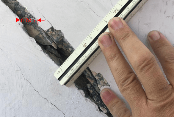
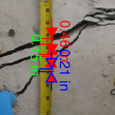
Yes at least 1/2 inch. I read ~0.8 inch, ~20mm


crackwidth_atycsj.png


crackwidth2_rocchh.png
 
epoxybot (Structural)20 Jun 19 05:19

Epoxybot, your post gave me a new clue. > The cracking of the bridge camouflaged from Pate the cracking of the bridge.
 
Re: the Wedge and PT anchors
As you know, the compressive stress is quite high under PT anchorages, especially with a bugle and several strands. Even single strand anchorages at slab edges need a pair of rebars just inside the anchor zone.
I do not have a specific recommendation except to urge caution with PT. The PT loads leave the structure "alive".
With regard to the Wedge I tried to sketch, in my mind the wedge is not directly under compression but the concrete within the influence of the PT anchor forces is compressed. So to distribute compression to the wedge there would be diagonal tension across the diagonals of the wedge. Perhaps the strains are not great and can be accommodated without cracking. Maybe it can be checked with the "strutt and tie" concept, with struts just inside the inclined sides and a tie across the formed edge. And maybe a #6 rebar would solve it. Maybe I am unnecessarily concerned.
Thank you for responding. If you can see (visualize) strains, deflections, and load paths you have the skills most necessary in structures. Just do not ignore what those skills are telling you. And I don't think you are likely to do that.
 
Vance said:
As you know, the compressive stress is quite high under PT anchorages, especially with a bugle and several strands.

Yeah, I've seen a few explode. And I've seen ones which didn't explode which should have! I can do the strut and tie anti burst diagrams but I wouldn't pretend to know how stresses behind PT anchorages really work. Add 1100 kips strut coming down from above and it gets very complex!
 
It has my name on it - I certainly hope it does not teach you how to get in a bind like the subject of this thread.
Seriously, I know nothing of the contents. But I applaud your curiosity. Can you find if it is used in a university course and where?
 
Status
Not open for further replies.

Part and Inventory Search

Sponsor