Eng-Tips is the largest engineering community on the Internet

Intelligent Work Forums for Engineering Professionals

  • Congratulations waross on being selected by the Tek-Tips community for having the most helpful posts in the forums last week. Way to Go!

Miami Pedestrian Bridge, Part X 50

Status
Not open for further replies.

JAE

Structural
Jun 27, 2000
15,432
0
36
US
A continuation of our discussion of this failure. Best to read the other threads first to avoid rehashing things already discussed.

Part I
thread815-436595

Part II
thread815-436699

Part III
thread815-436802

Part IV
thread815-436924

Part V
thread815-437029

Part VI
thread815-438451

Part VII
thread815-438966

Part VIII
thread815-440072

Part IX
thread815-451175


Check out Eng-Tips Forum's Policies here:
faq731-376
 
Replies continue below

Recommended for you

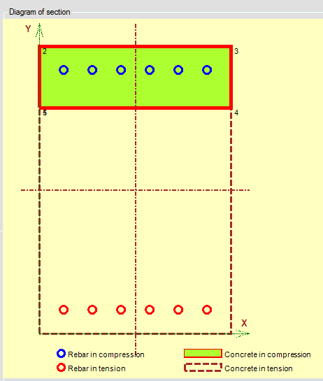
I hope to stop at its track that in all international reinforced concrete design codes (USA, Canada, Euro code, Chinese, Australia...) has a stress strain curve for concrete in compression peaks at 0.003 or 0.0035 strain but no tensile strain is allowed.

Omitting the tension in concrete is just a good engineering practice and does not necessarily representing 100% the actual situation. It is there really to simplify the calculation and to capture the safest approach to evaluate the member's capacity. If the tensile strength of concrete is included the calculation could be 10 times more complicated but with very little gain in accuracy. Anybody who has done section analysis of a reinforced concrete section would know the neutral axis can vary with load and concrete does crack at modest tensile strain well before the structure collapses.

On the practical side a structural concrete will have 3,500psi or 25kN/mm2 cylinder strength. Most concrete codes I came across in the past allow maximum tensile stress of 1 to 2 kN/mm2 or 145 to 300psi so tensile contribution by concrete in most cases is insignificant.

In reinforced concrete designs all tensile concrete area under the neutral axis is always assumed to contribute no tensile resistance. This has been always the case when reinforced concrete design changed from elastic theory to limit state design.

Capturex_ac2a4t.png


It makes sense because the capacity of a reinforced concrete section will be at its maximum limit when the compressive strain reaches 0.003 (standard to all North American codes). By inspection the maximum tensile strain in concrete would be even more. It is commonly believe the tensile zone in the concrete could develop micro cracks possibly not visible but would be the discontinuity for concrete offering tensile resistance at the ultimate limit state.

If tensile concrete strength were to be considered there is always limited by a specified strain in the tensile reinforcement and applicable only for the serviceability state (working condition).
 
Vance Wiley (Structural) said:
Also the final outcome was already determined when that photo was taken.

Finally I got someone agreed by just looking at the cracks in the photo would be enough to know the bridge has bone before the collpase.

In an update NTSB published these photos and concluded there has been a flaw in the design. The root cause of failure has been cast in stone.

OSHA report quoted a nonstructural crack could be less than 1/2" in depth but the bridge prior to collapse had photos showing crack depths of 3",4" and 7".

 
Recent ENR articles:

May 16 - Spreading Cracks On FIU Bridge Failed to Alarm Project Team (mentioned by jrs_87 (Mechanical) 17 May 19 09:45)
Richard Rice, a certified forensic engineer and president with Mutual Engineering, Hampton, Ga, said that he’s “been in that meeting” discussing mysterious cracking, citing his involvement with the shutdown of a parking garage at Hartsfield-Jackson Atlanta International Airport in the late 1980s, over what turned out to be minor surface cracking in some precast double-tees.

The firm he was working for at the time stopped work “because we had a duty to protect life and property.” By comparison, the cracks occurring on the FIU bridge “were astonishing” in size, Rice says.

June 12 - OSHA Investigation Slams FIGG for FIU Bridge Collapse
 
Quote from ENR article (Bridge Designer Testifies on Evidence One Day After OSHA Slams FIGG)

The [OSHA] report doesn’t solve all mysteries about what occurred.​
 
jrs_87 said:
The [OSHA] report doesn’t solve all mysteries about what occurred.
I agree. And I wonder if perhaps OSHA overstepped its authority here - when choosing who to blame for the whole thing, particularly the design shortcomings. I can see pointing out those who should have recognized an unsafe condition and who failed to act. (Understatement of the decade relative to bridges).
I thought their responsibility was addressing the placing of employees in unsafe conditions. Not who caused an unsafe condition of this magnitude which was, in some minds, not unsafe. Particularly with a pending NTSB investigation of much greater detail.
I suspect most parties will wait for the NTSB report. But I do appreciate the information presented in the OSHA report. It has provided insight into the actual failure.
 
I hope none of us would be stupid enough to believe the statement in the recent ENR article posted by
SFCharlie (Computer).


The structure failed before an additional part of the bridge, called the back span, and another pylon would have reduced the load on a critical connection of the unusual, single concrete truss design.


The doomed span was placed on the piers as a stand alone structure according to the submitted design documents. Everybody knows that.

If the bridge were unsafe without the back span and another pylon then this doomed span should never be allowed to be installed unaided above the live traffic.
 
saikee119 said:
I hope none of us would be stupid enough to believe the statement in the recent ENR article

The May 16 ENR article included this sentence:
Cables from a 109-ft-high central pylon, not yet built at the time of the collapse, would add stability, according to the design-build proposal.

This seems to falsely imply that the missing pylon and faux cables (actually steel pipes) were a contributing factor.
 
saikee119 (Structural)20 Jun 19 20:47

I agree with your post completely. Yes the span was intended to be stand alone, not dependent on subspan and pylon, but at what load? This also begs the question, if 11 needs backspan, why does 2 not? This is oversimplification for the sake of argument.
 
Saikee said:
has a stress strain curve for concrete in compression peaks at 0.003 or 0.0035 strain but no tensile strain is allowed.

In practice reinforced concrete depends heavily upon tensile stresses and strains. Structures would immediately collapse if concrete tensile capacity fell to zero.

We keep tensile stresses within acceptable limits, eg by requiring additional transverse reinforcement when tension exceeds certain limits (aka “shear reinforcement”), and by ensuring that bars laps are long enough that the resulting tensile forces don’t fracture the concrete, etc

In some cases we forbid relying on tension entirely, eg in critical flexural zones like you showed. But don’t confuse that with thinking we never rely on concrete in tension.
 
jrs_87 said:
We were all trained in risk management in grade school

What Do Aesop’s Fables and Risk Management Frameworks Have in Common?
The stories are simple to understand and use human and animal characters to describe how to make the right decision when faced with situations of uncertainty and complex ethical dilemmas.
Risk management, like Aesop’s Fables and early medicine, has been around for centuries. Unfortunately, the diagnostic tools to manage risks are still in the early stages of sophistication. Many risk professionals still diagnose their corporate patients based on a set of symptoms, without understanding the root causes underlying the illness.
 
Tomfh (Structural),

I think we can agree that in tension zone the rebar need to be gripped by the concrete to develop the full material stress in steel. I am not sure such adhesion between concrete and steel can be classified as the concrete tension. In any case such adhesion is not used in the computation of the section capacity against the combination of axial force and bending moments.

jrs_87 (Mechanical)

The 1/2 end has a side span but 11/12 does not. Only a staircase platform with a lift well has been proposed at the 11/12 end. When fully built the staircase and lift well could have a small contribution to restrain 11/12 from pushing out. If 11/12 cannot stand on its own it is doomed.
 
saikee119 said:
The 1/2 end has a side span but 11/12 does not. Only a staircase platform with a lift well has been proposed at the 11/12 end. When fully built the staircase and lift well could have a small contribution to restrain 11/12 from pushing out. If 11/12 cannot stand on its own it is doomed.

Nitpick: I think you have that backwards. The 11/12 note was on the pier where it would have abutted the back span. It's the 1/2 end that was to be on the landing with the staircase.
 
saikee119 said:
The 1/2 end has a side span
The stairwell is intentionally separated from the bridge by an expansion joint. The South end and North end are resting on slick low friction bearing pads to allow expansion and contraction. Both spans are anchored to the pylon beside the canal to stabilize the entire structure.
Member 2 and member 11 simply had to perform their task (if you will) without failure for this truss to work and be safe.
No provisions were apparent in the drawings I have seen on this forum which could have anchored or restrained the 2000 kips of factored horizontal force that would develop at node 11/12 and the deck. To say the back span would have stopped this is defensive rhetoric without basis. It is a fantasy wish and if that is all there is to grasp onto to save ones career, that career is already gone.
If I recall correctly, the total PT force longitudinally in the deck was about 2600 kips. The northward thrust of 11 at the deck surface was about 2000 kips factored TL. They would have to connect about 80% of the longit PT strands of the main span to the back span to restrain (or capture) node 11/12. Capture is actually a good word in this case - perhaps slightly Freudian in nature, because the node 11/12 had actually "escaped".
 
hpaircraft (Aeronautics)20 Jun 19 22:51

The 1/2 node diaphragm was simply supported by two bearings. No other connection to pier. North diaphragm was much smaller, which begs the question, did it depend on yet to be placed elements to be robust? It is suspect that they compromised the north end in size to fit the pylon and backspan on the landing. Also, it seems the complete bridge seems to call for PT tendons in the canopy from end to end, crossing through the pylon.
 
Status
Not open for further replies.
Back
Top