Two photos, Fig 61 and Fig65, in the OSHA report caught my attention.
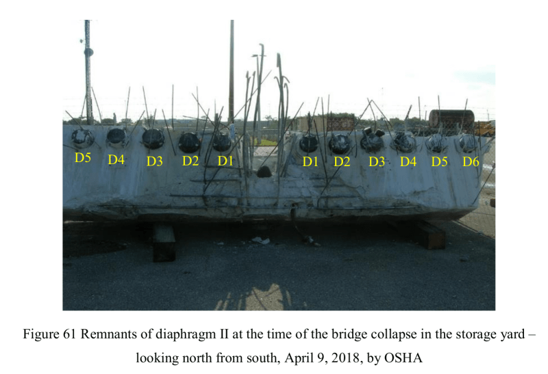
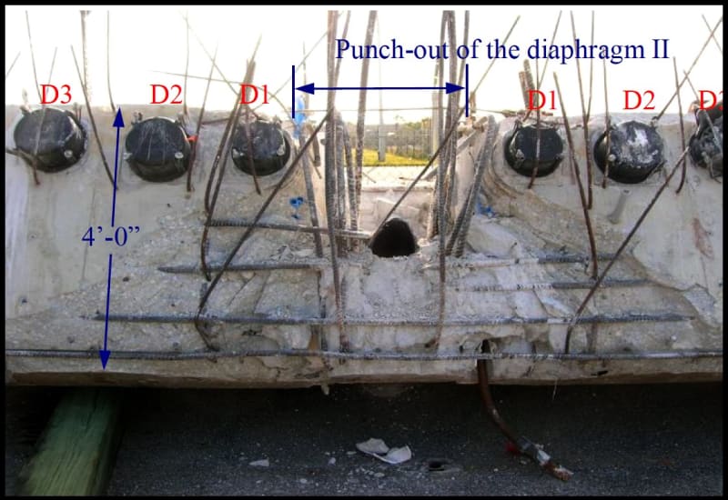
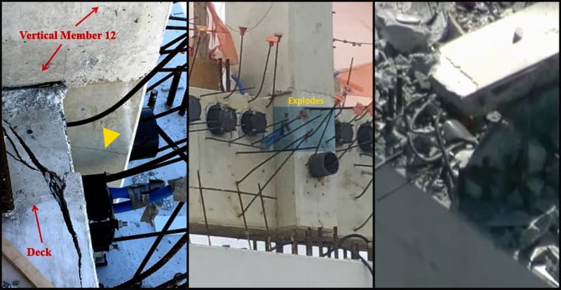
The Fig61 shows all the vertical rebar were intact after the collapse. In that the steel did not shear off like the concrete did but just debonded and separated from the spalled concrete. They were hardly bend or yielded. Most have the original 90-degree bends remain surprisingly in good shape after they came off off the concrete Member 12.
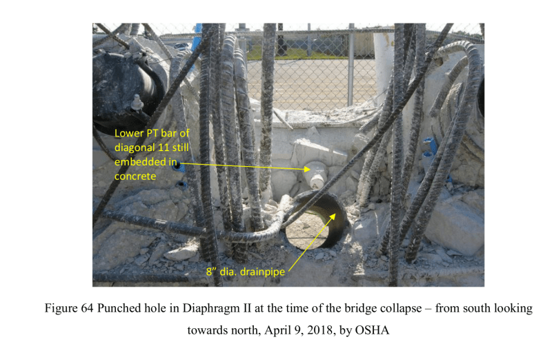
My concern is the vertical rebar of Member 12, seen from the OSHA report photo Fig61 and Fig64, did not participate much in resisting the Member 12 (together with diagonal Member 11) from being pushing outward during the collapse and none of them failed by shear. This would suggest the bulk of the resistance to prevent failure was the shear strength of the concrete alone. If any the rebar was designed to resist shear in Member 12 then the design simply did not replicate what has happened in the field.
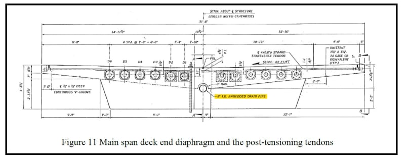
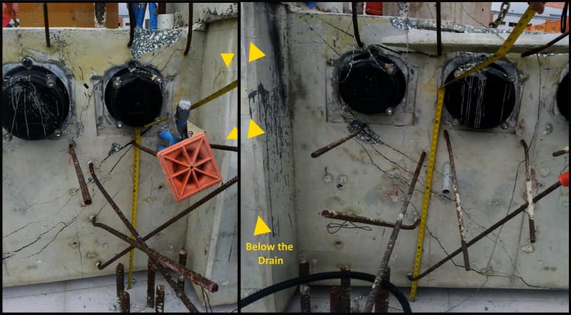
This is most likely due to the poor structural arrangement at this location where a 8” (ID) diameter pipe sleeeve was cast horizontally for the drainage allowance. With Member 12 only 1’9” wide the 8” internal diameter sleeve would have left only about 6” concrete necking on either side of the pipe sleeve. After taking the rebar size into consideration each necking has less than 3” concrete on either side of the rebar. When Member 12&11 were pushed out of position the concrete near the pipe sleeve simply blew out and disintergrated leaving the rebar behind.
No doubt many would argue the concrete area is wider than the Member 12 as it was cast partially into the deck. However the deck has been compressed axially to deflect inward but the Member 12&11 were pushed outward so there are clear and well established shear planes between them. To make the case worse there was a construction joint, acting as a plane of weakness, between the deck and the Member 12&11. OSHA report has provided photos on the cracks and spalling at this interface prior to the collapse.
Since the majority of the rebar at the failure location remains in their original positions and suffered no shear failure the evidence would highlight a serious deficiency that the concrete member sizes there were inadequate as they were unable to produce a common strain between steel and concrete. In other word the concrete had insufficent mass to transfer its stresses into the steel reinforcement. In properly designed reinforced concrete there should be no slip in strain between reinforcing steel and concrete.
It is quite possible had the 8” ID sleeve been omitted or relocated elsewhere the FIU bridge might still exit today or the fialure pattern would have to be substantially different.
![[flame]](/data/assets/smilies/flame.gif "[flame] [flame]")