Eng-Tips is the largest engineering community on the Internet

Intelligent Work Forums for Engineering Professionals

  • Congratulations waross on being selected by the Tek-Tips community for having the most helpful posts in the forums last week. Way to Go!

Miami Pedestrian Bridge, Part X 50

Status
Not open for further replies.

JAE

Structural
Jun 27, 2000
15,432
0
36
US
A continuation of our discussion of this failure. Best to read the other threads first to avoid rehashing things already discussed.

Part I
thread815-436595

Part II
thread815-436699

Part III
thread815-436802

Part IV
thread815-436924

Part V
thread815-437029

Part VI
thread815-438451

Part VII
thread815-438966

Part VIII
thread815-440072

Part IX
thread815-451175


Check out Eng-Tips Forum's Policies here:
faq731-376
 
Replies continue below

Recommended for you

jrs_87 said:
The above guidelines 1 and 5 were clearly not followed.
.....
resentment of Government/OSHA play a part. My father posted cartoons that mocked OSHA on the office trailer walls in the 70's.

IMO there are good reasons why OSHA are mocked. The greater focus (at least in my experience) is on the A in OSHA. It is about writing the rules to cover your ass and then getting on with the job. Rather than doing the job while thinking about safety at ever step. Rule 8 is typical of this. Do you really think this rule is adhered to to the letter? If you are going to write rules don't write ones that are going to be ignored in the course of a real job.

{end rant}
 
human909 said:
{end rant}
Allow me to continue rant.
In my experience, while some OSHA rules are clear, most include enough legalese and ambiguity that they can always claim that the rules were not followed, so no matter how hard you try, they can always find a violation of some sort. The only way to prevent it is to never have them visit your job site.
{end rant]

Brad Waybright

It's all okay as long as it's okay.
 
I questioned before if emergency shim was ever placed. Turns out it was, on 3/14/18.

OSHA Report, page 74
MCM and TSG placed the recommended shim (steel instead of plastic) under the diaphragm II.​

2019-06-18_1_zg4wcw.png
 
The EOR is much more than a PE:
W. Denney Pate, P.E. is a Senior Vice President and Principal Bridge Engineer with FIGG and is credited with the creation of the cradle system. He serves on the PTI Cable Stayed Bridge Committee, the FHWA Virtual Bridge Committee, is a professional engineer in 16 states and certified by NCEES.​

This was a simple project by FIGG standards, yet demigod Pate somehow found himself "in over his head" despite working comfortably in deep waters most of his career. His erratic behavior during the weeks leading up to the collapse hint at severe pressures that compromised his professional integrity, overrode his responsibilities as a company VP, and ruined his personal legacy.

The big WHY in the final weeks wasn't "Why didn't Pate do the right thing?", it's why wasn't he removed from the decision process when it became crystal clear he was compromised or impaired. Why wasn't there a mechanism that allowed a group of informed, concerned individuals to combine their opinions and override his.

The older I get the more concerned I become about this "too big to fail, too big to nail, too big to jail" mentality that is gaining popularity. Allowing any individual or entity to have unrestricted, concentrated power is just not healthy.

End of rant. I don't have any answers.... I hope the younger people figure it out before it's too late.
 
In computer engineering, when we went from hardware prototypes to software prototypes (simulation), we had to turn both the engineers and management views upside down. Bug (design failures) in hardware prototypes are expensive, so "Bug are bad" prevaled. In a software prototype "Bug found and fixed" are good. We learned to keep a chart of bugs found. When the bug finding rate dropped, we turned up the pressure to find more bugs. So, engineers can turn management around when they can show cost savings. (Yes, greatly simplified for brevity.)
 
Screenshot_from_2019-06-18_17-31-41_sqlxqb.png


The above diagram was posted by gwiderman on 12 Jun 19 23:01. It is NOT the official version from FIGG to fix the failed joint but an excellent representation of what FIGG had proposed according to Page 76 of the OSHA report.

Screenshot_from_2019-06-18_17-33-51_gju7te.png


In the OSHA report despite FIGG considered the cracked 11/12 joint not a safety concern it nevertheless had conceded that the structural adequacy of the cracked joint was an issue during the construction stage when it had no end restraint. Such restraint would of course be provided by the erection of the side span had the bridge been able to achieve completion.

The need to strengthen the bridge by passing some of the loads back to 9/10 is a clear admission by FIGG that its design was faulty. According to OSHA report there is apparently a reference in the Minutes of the last meeting in March 15 2018 that FIGG had promised a temporary strengthening scheme to be delivered to MCM by March 17 2018. A strengthening scheme is significant evidence that the exiting design was inadequate as new materials must be introduced to alter the load distribution of the bridge to halt the growing cracks.

The proposal to introduce additional restraints to strengthen the bridge and the manner of the bridge failed on March 15 tell me that FIGG knew and had identified the risk but failed to act in time to prevent the collapse.

Therefore it is now cast in stone that FIGG was of the opinion that the condition of the bridge with cracked 11/12, as documented in OSHA and NTSB reports, was not unsafe and remedial work could still be instructed and carried out on it while live traffic passing underneath. FIGG had on recorded, in the March 15 2018 meeting, has accepted that the bridge did require to be strengthened above its existing design and such strengthening scheme was due to be delivered to MCM on March 17 2018. It is also significant in the meeting that FIGG proposed to restrain the node as 11/12 was seemingly moving away from its designed position.

The photographic evidence in OSHA report would suggest 11/12 moved outward away from its support, the deck snapped and dropped onto the ground relatively intact as a single entity. Additional breaking and spalling of concrete could have taken place as the consequential effects from the separation of 11/12 from the deck. Much the 11/12 was still resting on top of the pier after the bridge failed. It would be obvious had the 11/12 been restrained in time and prevented from moving away from its designed position the bridge if were to collapse must have a totally different failure mode. Its 11/12 and the deck could be resting "together" on the pier in the same manner as 1/2 at the bridge opposite end did after the March 15 collapse.

The fact the bridge collapsed before FIGG’s strengthening scheme could be devised is a good testimony on the technical competency of FIGG on the matter. Its insistence without reservation at all time that the bridge, with growing cracks, were safe had not only been unhelpful but fatal to the workmen working on it and the motorists public using the highway beneath the bridge.
 
saikee119 (Structural)18 Jun 19 17:23 The fact the bridge collapsed before FIGG’s strengthening scheme could be devised is a good testimony on the technical competency of FIGG on the matter.
Being sarcastic, right?
I still question this statement/position by FIGG: "Such restraint would of course be provided by the erection of the side span had the bridge been able to achieve completion. "
Could someone identify the elements/parts in the closure strip over the Pylon which will provide 2000 kips of tension tie between the north and main spans?
 
TheGreenLama said:
We do have a clamping force in Area1, so certainly concrete shear resistance is going to develop,

First comment on the above: I disagree. I do not perceive any clamping force across the plane that sheered out in a "punch out" failure.

Second comment on the above: Even if there were clamping force allowing elevated sheer force in the concrete (there is not), what about elevated sheer resistance in the steel ? There is no steel. Therefore, there is going to be a tensile failure due to lack of steel!

In other words, there is no tie BETWEEN the ~1200 kips travelling north in diagonal #11 on the one hand, and the ~1200kips travelling south in the deck on the other hand. Without any TENSILE tie between those two massively loaded elements, they are going to part company. As indeed they did, with fatal effect. Newton's second law says that when you have an UNBALANCED force acting on an object, that object is going to accelerate. In this case, a steel tie would have provided the balancing force. But, there was no steel tie. This point is about as elementary as structural design can get.

I would appreciate any enlightenment on this point of analysis.
 
Just some information for the curious. Barnhart's contract was for $435,160.00. The charges for delay to Barnhart's execution of the work were: $24,000 to mobilize & demobilize personnel & $72,000/week for equipment on Standby.

It is pretty clear in video posted by MikeW7 (Electrical) to his Whirled Gnus YouTube page that cracking started very early in the detensioning of member 11. Video: 
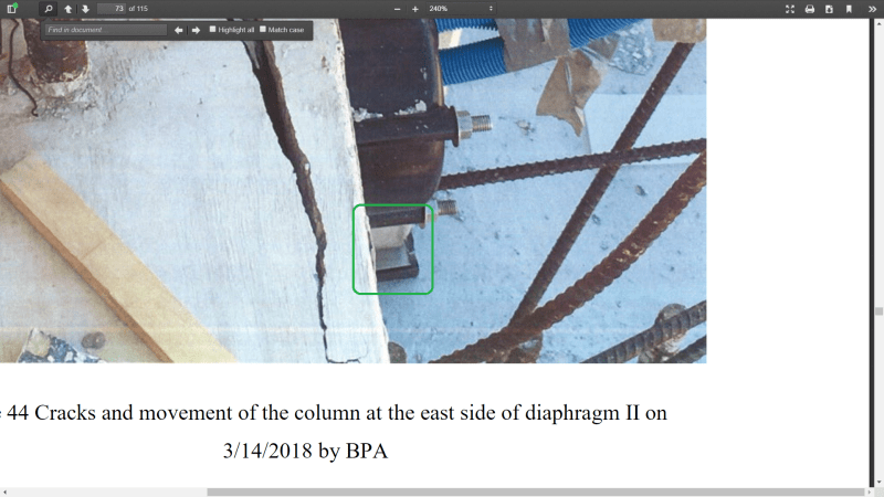
Move part 4 - N view at the 1:40 mark. People start inspecting the 11/12 node and the canopy crew stops work for a time.

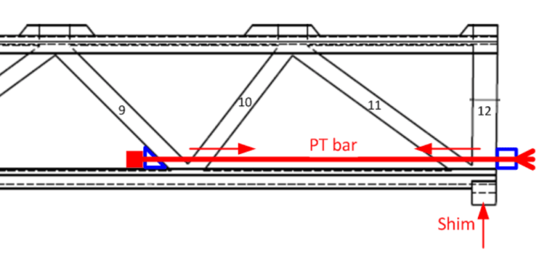
The tensioning sequence for members 2 & 11 both start with the longer & lower PT bar. Wouldn't detensioning be the reverse order? The OSHA report states VSL had completed the final load on the upper bar & was just finishing apply the final load to the lower PT bar, when the collapse took place. This is the opposite to the tensioning sequence in the plans. It is worth noting that the schedule for the PT tensioning of member 2 & 11 both have "A" - "B" designations. In member 2, "A" is the longer PT bar & in member 11, "B" is the longer PT bar. VSL should have color coded these bars in the field to eliminate any confusion. In what order did VSL originally tension & detension members 2 & 11? (EDIT: Perhaps I'm wrong. Maybe they started & finished with the lower PT bar.)

On an all together different tack, it is really troubling that in all the years & money that went into this project and the projections of future pedestrian use and how this was a project hand-in-hand with the City of Sweetwater, with the goal of pedestrian SAFETY, along with the glorification of the restoration BROTHERS TO THE RESCUE MEMORIAL PLAZA (old foot bridge across canal); the City of Sweetwater has not spent one dime on pedestrian safety. There is not one marked crosswalk, from one side of 109th Ave. to the other for blocks. You would think that with all the construction that was planned and with STUDENTS living in the existing 109 Tower, that the supposed primary goal of "pedestrian safety" in a construction zone, would have been a top priority. The handicap access to the BROTHERS TO THE RESCUE MEMORIAL PLAZA hasn't changed since 2011. It is as if, the moment the FIU pedestrian bridge moved from one side of 109th ave to the other, the City of Sweetwater was off the hook to do any improvements. It all speaks to a ridiculous degree of Hypocrisy from the TIGER Grant to the point of Collapse by the Owners, FIU & Sweetwater.


Days after this accident, this thread strongly questioned the planning for the post-move temporary state. In the early days of this thread it was speculated FIGG did expect 11/12 node to be deficient, but with respect to full load only.

Does anyone know the allowance the member 11 PT bars had in their ducts? I anticipate that while the bar was slack and the node was slipping, the duct pathway may have curved or pinched. This may pose problem when bar re-straightens in curved duct.
 
Post Edited Great post! Report jrs_87 (Mechanical)18 Jun 19 18:58 said:
the duct pathway may have curved or pinched.
The PT rod ducts were cast into the concrete members and absent observable distortions of the concrete member the duct pathway should not change a lot. It could have pinched at the interface with the deck, where member 11 was sliding and the PT rod crossed the shear plane.
The photo of the longitudinal crack up the slope in member 11 may indicate cracking from leveraging of the upper PT from the sliding action of 11 against the bar just above the deck surface.
 
Vance Wiley said:
Could someone identify the elements/parts in the closure strip over the Pylon which will provide 2000 kips of tension tie between the north and main spans?

That's kind of the $64,000 question. I have not seen any sign of a substantial connection between the span and back span in the drawings so far available. But I wonder if Figg might have been hatching a plan to tie onto the ends of some or all of the longitudinal PT rods and connect them to their counterparts in the back span. They could have used the same coupler nuts that the Hyatt Skywalk fabricators passed up.
 
Thanks JRS_87, your post was a little long to requote, no offense is intended.

My basic line of reasoning for the 11/12/deck system is that it is a strut and tie system, looks a lot like the strut and tie method diagrams in the Codes, not so much the shear friction diagrams.

From not quite 40 years ago in my Mechanics of Materials class (the text was literally titled "Mechanics of Materials", still have the book an arms length away at work) it is taught that loads are distributed based on relative stiffness. Everyone remembers, 1 square inch steel rod inside a 9 square inch pipe with rigid end plates compressed axially. Ninety percent of the load is carried by the 9 square inch pipe. Either an aluminum rod or pipe was left for homework it seems.

Anyway, far and away the axial stiffness of the members will exceed the flexural and shear stiffness of the members especially once the members begin to crack. Although I will give that the flexure and shear stiffness of the top and bottom decks would have been significant. And all forces on all members should be considered during detailed design.

With the disclaimer that I do not have access to all the calculations that may been performed by EOR or the Peer Reviewer, submittal calculation often exclude significant amounts of calculations actually performed (another topic for another thread). I have not found any analysis for how to resolve the forces for the horizontal loads, either strut and tie or "classic" beam analysis. FIGG appears to try to accomplish this for the vertical loads in the presentation the morning of the collapse, both strut and tie and "classic" beam. May have missed analysis reviewing the submittal calculations that are available.

For Member 11, as mentioned in one of my previous posts, there appears to be a lack of ties along the compression member into the nodal region, no ties between the top of concrete between Members 11/12 down into the top of the deck and nodal region in the deck.

For a horizontal member that could be capable of distributing loads to the longitudinal post tensioning strands, essentially the tie for the strut and tie model, the reinforcement appears to be especially poorly detailed. Only two #8 bars appear to be continuous across the diaphragm on what would be the tension face, 1-8S06 & 1 8S05, the rest appear to hook near the center line to accommodate the drain pipe. Even the two that were shown in the drawings do not appear to be visible in the OSHAA photos of the end of the diaphragm, could have been cut of for material analysis or completely sheared off during the collapse. For very simple math and geometry. Two #8s Tension T=2*0.79*60 = 95k, At 45 degrees, strut each side, Horizontal force = 2*sin(45)*T = 2*0.707*95 = 135k. Very rough, I know, but appears to be an order of magnitude less than required. I am at loss, as others have stated, why there wasn't post tensioning at the center, the drain pipe could have been accommodated in another manner, and why the post tensioning that would have been most effective to resist horizontal loads, D1 & D2, had less strands than D2 thru D6 further away.

For "classic" beam analysis, consider a more typical case, a very deep beam spanning horizontally with a very heavy downward vertical load attached over a small area at the bottom. See the problem, no one would use shear friction to transfer the vertical load into the beam on the tension face.
 
Vance said:
The photo of the longitudinal crack up the slope in member 11 may indicate cracking from leveraging of the upper PT from the sliding action of 11 against the bar just above the deck surface

Agree. The top PT bar was digging in and breaking the top off of 11. This rod eventually burst out, and the lower PT rod had greater edge distance and sheared off.

Vance said:
not so much the shear friction diagrams

That’s right. It’s not a failure along a horizontal line, there’s only some areas where that occured. The rest is classic concrete in tension cone failure. Thus shear friction is not very relevant. It simply didn’t fail along a horizontal shear plane (except between a limited portion of member 11 where it meets the deck). The structure found the easiest path to failure, and it wasn’t a shear friction failure. Shear friction capacity wasn’t critical.
 
Vance Wiley said:
Could someone identify the elements/parts in the closure strip over the Pylon which will provide 2000 kips of tension tie between the north and main spans?

If I understand your question correctly, my take on this is that, as FIGG saw no problems with their original design, there was no large force to accommodate. In their eyes the main span was just a self-supporting precast girder. The back span, being cast in place, would impart a horizontal force from the diagonal into the pylon. I'm assuming this was designed for. Now after problems developed, that's a whole other story.
 
3TheGreenLama (Structural)17 Jun 19 21:45
FortyYearsExperience
Re Shear friction and cold joint at 11/12 to deck.
"Area 1: bars 7S01 lack adequate development length;"
The calcs by TGL seem to dismiss any contribution from the 4 - #7 hoops "7S01" in zone A1. Eight #7 bars cross the shear plane, with As=4.8 sq in. It seems to me these bars can contribute some to the shear friction present. Iowa DOT spreadsheet, AASHTO 2017, looks like development length of a #7 is 18" in 8.5 ksi concrete. So these bars had a 90 degree bend (50% in the old days) and 8"/18" or 44% length = 94% . Or maybe only 8"/(0.8X18)=55% of optimum capacity. Of course all bets are off when the steel yields and the joint slip exceeds the 1/4 inch amplitude for an intentionally roughened surface or, in my mind, when slip exceeds about zero for a smooth surface.
I would like to see a really detailed examination of the "sheared" #7s. Did they actually shear or did they fail in tension? Where are the missing tops of the hoops?
And a comment on this part - "bars 7S03 are inclined in wrong direction ". Being parallel to the action of 11, they actually served to resist the axial force and maybe relieved some of the normal force which was counted on to mobilize the shear friction across the cold joint.
But for sure, as FortyYearsExperience says, the normal to sides "clamping force" Figg counted on did not develop and that block simply blew out the end.
I vote for a welded steel socket for member 11 of about 400 2500 pounds with a pair of 30 foot long plates totaling 40 to 50 sq inches and a few hundred welded studs to anchor the socket to the deck. Now I feel like we are in the ballpark.


The post accident photos show steel plates leaning against the pier. What possible use would such large plates be for? Was the emergency shim cut from it? Could it be they were fabricating something? Any ideas?

I see in OSHA photos, at least one uhmw shim ended up on walkway. This means when diaphragm slid off landing, the shims remained. Then vacuum of falling deck pulled them down.

I examined photo of form-work in OSHA photo. Questions in my mind afterwards? How would they access deck cj to roughen it? I see in closeup of deck cracks what appear to be leaves, wood chips (,or just JPG aberrations). Could the nature of the tall forms have lead to debris build up at deck cold joint?

Finally, why was the construction joint at the base of 12 so sloppy? Specificity at the step in width. (Member 12 is wider than the diaphragm key.)
 
That is kinda how we view a real ordinary truss. Mixing the different materials and concepts leaves room for lots of things to be missing.
Also a "strut and tie" system is where I think FortyYearsExperience would visualize and approach this.
And lastly, that is a good way to describe this structure.
And I agree there is an obvious shortage of confinement reinforcing at critical areas.
 
jrs_87 (Mechanical)19 Jun 19 03:14 said:
How would they access deck cj to roughen it?
In building construction they would prepare the construction joint before constructing vertical forms, then leave a lower removable panel off the forms to clean sawdust and such.
Then pour the first 2 or 3 inches as a slurry using the approved concrete mix with the aggregate removed, because the cream of the mix sticks to the reinforcing and creates a lean mix with rock pockets in the bottom of wall and column pours if this is not addressed. If it is possible to get a hose to the bottom of the pour and deliver the concrete without losing paste on the reinforcing, the rich mix slurry can be avoided.
 
Status
Not open for further replies.
Back
Top