Eng-Tips is the largest engineering community on the Internet

Intelligent Work Forums for Engineering Professionals

  • Congratulations waross on being selected by the Tek-Tips community for having the most helpful posts in the forums last week. Way to Go!

Miami Pedestrian Bridge, Part XI 32

Status
Not open for further replies.

JAE

Structural
Jun 27, 2000
15,432
0
36
US
A continuation of our discussion of this failure. Best to read the other threads first to avoid rehashing things already discussed.

Part I
thread815-436595

Part II
thread815-436699

Part III
thread815-436802

Part IV
thread815-436924

Part V
thread815-437029

Part VI
thread815-438451

Part VII
thread815-438966

Part VIII
thread815-440072

Part IX
thread815-451175

Part X
thread815-454618


Check out Eng-Tips Forum's Policies here:
faq731-376
 
Replies continue below

Recommended for you

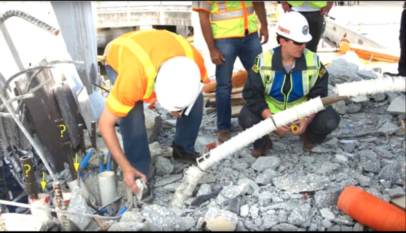
There are 3#11 vertical bars that were suppose to be on the inside face of member #12 missing from the deck. It looks like they were not well embeded into the deck (assuming they were pulled out and stayed with member #12). The drawings show the centre #11 vertical bar offset to clear the drain pipe. Although the offset shown on the drawings does not look like it is sufficient to clear the pipe. This could be one of the contributing reasons why the shear plane dips down below member #12. It looks like the bars should have been better embeded than they were. I was just going over the latest photos and notices this
 
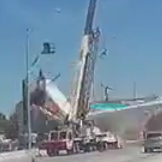
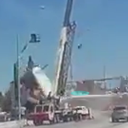
I prepared a cropped, enlarged version of the truck-cam video that is as free of artifacts as I can make it. A section of the original video was cropped to 240x135, then I resized it by a factor of 400% to 960x540 using nearest neighbor interpolation, both operations done with native filters built into VirtualDub2. From what I've read, nearest neighbor interpolation doesn't introduce many artifacts because it simply moves pixels apart and inserts the value of the nearest neighbor. It enlarges an image while preserving the "chunky" nature of the original pixelated image.

I also created individual images for each frame in the cropped video, and they are named after the frame number in the original video - Frame0072.jpeg through Frame0086.jpeg. The JPEGs were saved at 100% quality.

I zipped the video and JPEGs into a single ZIP file that can be downloaded with this Link. The video format is the ancient AVI windows format because that was all I could coax out of VD2. If someone asks I will convert it to MP4, but no guarantees on the quality.

My observations about the frames:
[ul]
[li]72-73-74 Nothing apparent[/li]
[li]75 - If you squint really hard and rub a magic nickle, you can just barely see the bottom of the deck move ever so slightly with respect to the traffic light beneath it. Collapse has begun. Or not. See the next frame.[/li]
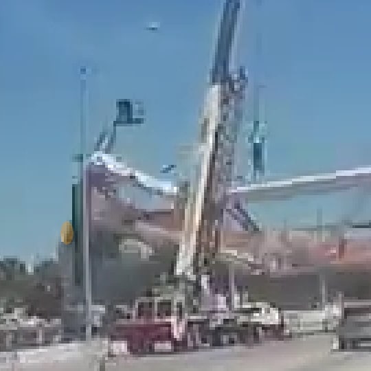
[li]76 - The deck and canopy are starting to drop, but member 11 does not appear to have moved much.[/li]
[li]77 - Member 11 still does not seem to have dropped or rotated much in comparison with the dropping of member 10 and the canopy.[/li]
[li]78 - Member 11 has started to move significantly. The canopy above member 12 has dropped slightly, so member 12 has been blown off the pier.[/li]
[li]79 - Member 12 and its attached canopy are in free-fall. The area around the 11-12 junction seems to be filled with debris, and the lower 20% of section 11 seems to have disintegrated.[/li]
[li]80 - The bottom of member 12 is plainly visible to the left of the pier, and the canopy attached to 12 has now dropped 3-4 feet, using the "falling man" for scale.[/li]
[li]81-82-83-84-85 - As the entire canopy continues to fall, the section attached firmly to member 12 causes it to rotate, and the bottom of 12 is pulled up and dragged onto the top of the pier.[/li]
[li]ADD: 82 - The north end of the deck is falling off the north pier. [/li]
[li]EDIT: 86 - The north end of the deck and the bottom of member 12 have reached their final resting places.[/li]
[li]86 - The bottom of member 12 has reached it's final resting place.[/li]
[/ul]

ADD: Here are links to the Whirled Gnus Playlists
And here is a link to all the individual videos sorted by age, with newest first.
 
Epoxybot said:
If a PT Rod did shear, it sheared when the canopy fell and pinned/sliced the PT Rod.

The lower PT rod certainly did break.

Remember it was passing thru the crack (which was nearly an inch wide), so it was likely acting as a dowel across the crack and would have been helping to hold the crack together. It failed when they tensioned it back up, which was probably what triggered the collapse, given that this rod was no longer contributing.
 
Tomfh said:
The lower PT rod certainly did break.

Remember it was passing thru the crack (which was nearly an inch wide), so it was likely acting as a dowel across the crack and would have been helping to hold the crack together. It failed when they tensioned it back up, which was probably what triggered the collapse, given that this rod was no longer contributing.

The rod could not have broken/sheared as part of the shear friction failure. It had to stay intact since it ripped through the bottom of #11 and ripped out all the ties as the deck fell to the ground. It essentially ripped out the back of #11 rather than shearing.
 
It is worth to examine how the span failed to distinguish the root cause from the consequential damages.

NTSB and OSHA photos indicate a gap of about 5mm or 1/4” in the cast-in duct in 11/12 before March 15. It would be safe to suggest 11/12 has deflected outward relative to the deck.

On March 15 Member 11 was re-stressed to nearly the original level, upper PT 280kips and lower PT 230kips, when the span failed.

The geometry of Member 11 tells us any additional outward deflection, from the re-stress, will flatter the angle resulting a higher horizontal force pushing outward.

(1) While the angle in member 11 progressively flattened and 11/12 outward movement increased the bridge reached a point that it was no longer able to support itself. It therefore quickly deflected downward. With increased curvature the deck would tilt at both bearing supports.

(2) When the bridge finally broken the deck profile changed from a curve to a “V”. This is important because horizontal distance between the two top points of the “V” is shorter than original deck length. This could cause the bridge to depart from the bearing supports.

(3) When the bridge was about to snap into a V the tilted deck could slide downward to clear the pier. This happened to the 11/12 while the south end, still with everything attached, was resting on top of the pier.

(4) The 11/12 joint was partially damaged prior to re-stress. The re-stress would inflict additional damage. The collapse mechanism flattened the Member 11 beyond the point of no return. Thus during collapse 11/12 was progressively moved outward while the broken deck pulled itself inward.

(5) The progressive separation of 11/12 from the deck facilitated the deck to leave the bearing support and drop to the ground while 11/12 was caught by the pier and did not fall.

(6) The shear weight of the dropping deck produced some consequential damages. Among them are lower PT peeled off from Member 11 and ripped open the confining shear links and a blow out of concrete when 11/12 was forcibly separated from the deck.
 
Earth314159 (Structural) was right. The lower PT rod did not shear but able to rip out the ties in Member 11 as depicted below.

Screenshot_from_2019-06-23_00-06-58_oojvwh.png


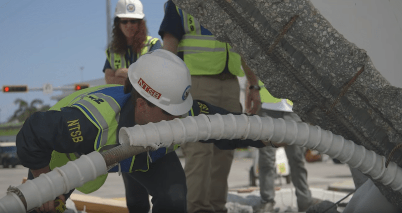
The plastic sleeve/duct was cut during the ties rip out. NTSB video shows the a number of ties rip open by the lower PT rod.

Screenshot_from_2019-06-23_00-22-03_klx8tx.png


I believe the sheared lower PT rod in OSHA report Fig 63 may have been artificially cut to show the construction joint. Apart from Fig 63 I could not find a reference the lower PT sheared elsewhere in the report.
 
I suspect the code in Florida is similar to other concrete codes. For most of the codes I know, the tie arrangements would not have meet code. Is the concrete code used in Florida different in this regard? How did they get away with this tie arrangement for the compression diagonals?
 
MikeW7 Thanks again for putting your time into the video. Here are my notes:

On image 74, potential worker on deck (green), potential debris blowing out north of 12 (pink)
74_czgsk7.jpg


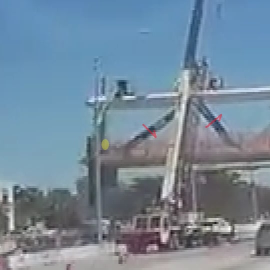
On image 75, potential puff of debris (yellow), potential deflection of 10 and 11 (red arrows)
75_kajg3n.jpg


On image 80, bottom of 12 dislodged off of diaphragm (orange)
80_nkrgdk.jpg


On image 82, potential furthest extent that PT rod is pushed through the canopy (cyan)
82_c9p5vj.jpg


On image 83, PT rod is sucked back in as the deck falls off the pylon (cyan)
83_mitqvw.jpg
 
I hope the NTSB takes the Miami-Dade Transit Operation Center to task for not recording the collapse on their Traffic Camera. They had two different protocols to save the feed in a 30 minute window. 1) they could have bookmarked the feed to prevent the system from dumping it & 2) every work-station had a one button record screen peripheral device at each keyboard. You know they got a nice Fed Grant for the brand new Upgrade of the center.
 
saikee119 said:
The information you asked took place on Sep 15 2016

Thank you saikee119. That is an astonishing piece of information. This redline drawing of the crack location was known in 2016, but the ultimate bridge designers ignored it. No doubt that was because they were unable to also draw free hand where the failure point would be, but had to rely on a huge and faulty computer program to tell them. As we now know, the computer program was filled with garbage.
 
Saikee said:
I believe the sheared lower PT rod in OSHA report Fig 63 may have been artificially cut to show the construction joint. Apart from Fig 63 I could not find a reference the lower PT sheared elsewhere in the report.

Ok.

I mistakenly assumed the caption "Lower PT bar of diagonal 11 sheared” meant sheared during the collapse, as opposed to cut off later.
 
Sym P. le (Mechanical) 23 Jun 19 01:10 said:
On image 74, potential worker on deck (green)...

I went back to the Collapse - N view video and that NW corner is where Hanson was standing just before the collapse. He was wandering back and forth from NW to NE corner of the deck, and at 2:30 he got on his knees to look at the east side of the 11-12 junction, then at 2:40 he was again on his knees at the west side. Here's the video, set to start at 2:20

 
If the lower rod of member 11 was passing thru the crack at a shallow angle and was anchored into deck wouldn't retensioning 11 pull the crack open?
 
@Mike - You're right. I had looked for him in the video but wasn't sure of his location or the time frame of the video but there are a bunch of indicators (delivery truck in background leaving yard) that he was standing in the corner at the collapse.
 
Sym P. le (Mechanical)23 Jun 19 01:59 - The new video is only 15 frames long, or 3 seconds real-time at 5fps, so Hanson didn't have time to move from his last position in the Collapse - N view video. I rechecked that video and he kneeled twice to look at the junction, the last time right before the collapse. Something bad was happening, and he knew it....
 
Tomfh said:
If the lower rod of member 11 was passing thru the crack at a shallow angle and was anchored into deck wouldn't retensioning 11 pull the crack open?

Yes, that is correct. It adds some clumping force to increase the friction capacity but it also increases the shear across the concrete surface which makes the whole condition worst.
 
epoxybot I had hoped that the NTSB had the traffic cam footage. I know it was captured by an iphone at about 4 iphone frames per traffic cam frame. I've looked at it frame by frame. The deck appears to crack diagonally (farther south on the east side.)


SF Charlie
Eng-Tips.com Forum Policies
 
Status
Not open for further replies.
Back
Top