Eng-Tips is the largest engineering community on the Internet

Intelligent Work Forums for Engineering Professionals

  • Congratulations waross on being selected by the Tek-Tips community for having the most helpful posts in the forums last week. Way to Go!

Miami Pedestrian Bridge, Part XI 32

Status
Not open for further replies.

JAE

Structural
Jun 27, 2000
15,432
0
36
US
A continuation of our discussion of this failure. Best to read the other threads first to avoid rehashing things already discussed.

Part I
thread815-436595

Part II
thread815-436699

Part III
thread815-436802

Part IV
thread815-436924

Part V
thread815-437029

Part VI
thread815-438451

Part VII
thread815-438966

Part VIII
thread815-440072

Part IX
thread815-451175

Part X
thread815-454618


Check out Eng-Tips Forum's Policies here:
faq731-376
 
Replies continue below

Recommended for you

SFCharlie (Computer) 23 Jun 19 03:04 said:
The deck appears to crack diagonally (farther south on the east side.)

That would explain why the canopy appears to tip toward the camera at frames 82-83, just as the deck hits the highway. I didn't want to say anything before, but to me less of the canopy top would be visible at the end (frames 84-85-86) if the canopy had remained level E-W as the deck settles on the ground. Ground images should provide some clarification.
 
Is it possible to damage Member 11 by the adopted construction sequence?

I open up this line of investigation after Tomfh raised the point and Earth314159 concurred.

Earth314159 (Structural) said:
Quote (Tomfh)
If the lower rod of member 11 was passing thru the crack at a shallow angle and was anchored into deck wouldn't retensioning 11 pull the crack open?
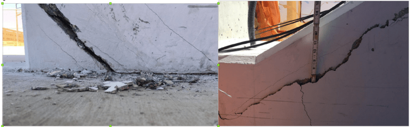
The evidence

(a) After collapse the bottom end of the Lower PT rod was attached to the deck. Its upper end was in the canopy

(b) Upper PT rod had both ends remained with the separated 11/12. Rod’s bottom end was on top of pier and the upper end in canopy.

(c) There was a construction joint between the deck and the separated 11/12.

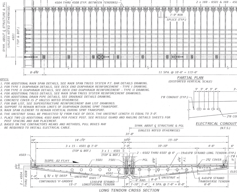
(d) This photo shows the the lower PT rod intercepts the last transverse PT rod, 4’-2.5” from the end, in the design. No transverse PT cold be installed to intercept the upper PT rod due to the obstruction by the longitudinal anchors. Evidently if the Lower PT rod were to be separated from the deck like the upper one it had to rip out the affected transverse PT rod and break up part of the deck but this did not happen.

Screenshot_from_2019-06-23_09-51-55_civvkm.png


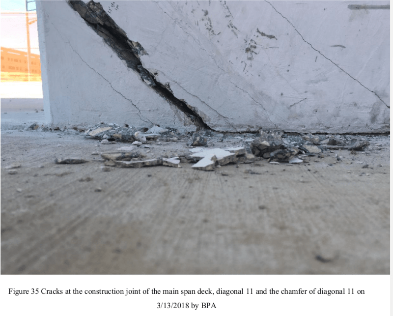
(e) An evidence showing the one PT rods effective on the deck while the other on 11/12 is OSHA report's Fig 35. Along the sloping crack in Member 11 the concrete on one side was still rigid with the deck but the other side was with 11/12 according to the condition of the construction joint.

Screenshot_from_2019-06-23_12-46-35_rts0jm.png


My interest now is how the two PT rods were de-tensioned. OSHA report does not mention the procedure. It would not be surprising the rod tension was removed in a single operation instead of by stages of 50kips per rod alternately.

If the stress were fully released in one rod while the other was not then there would be a substantial stress differential between the deck and 11/12 due the fact one rod was effectively tied to the deck and the other to 11/12. The stress differential was also exacerbated by the construction joint.

The construction photos and the OSHA report have already confirmed the serious crack damage occurred immediately after the stress in 11 was removed on March 10.

Theoretically the stress release in 11, even in stages of 50kips per rod alternately, could still inflict damage to 11/12 joint with the deck because structurally one rod pulls the deck while the other 11/12 over a plane of weakness created by the construction joint. In stages the damage would be less.

When 11 was re-stressed again on March 15 every application of the staged 50kips to either rod could grind the construction joint if each rod was able to pull it own part of the span. The construction joint (CJ) between 11/12 with the deck looks increasingly likely to play a key role in the demise of the bridge due to the different effectiveness of the two PT rod anchors on either side of the CJ.

It is also interesting to note on June 19 an ENR article reported "FIGG hinted that construction-related activities, rather than design, could be chiefly to blame. According to the statement, FIGG claimed the (OSHA) report “does not include an evaluation of many important factors pertinent to the construction process leading up to the accident. " Does this open the door for FIGG to blame MCM for the bad CJ?
 
saikee119 (Structural)23 Jun 19 10:14 said:
Does this open the door for FIGG to blame MCM for the bad CJ?
FIGG specified the casting of the deck before the "diagonal and vertical members"
FIGG_phase_2_foh3ul.jpg

FIGG ordered the detensioning.
The cracks were growing before the retensioning.
FIGG ordered the retensioning.
FIGG said safety was not an issue.
How is this MCMs fault, not FIGGs?

SF Charlie
Eng-Tips.com Forum Policies
 
SFCharlie (Computer),

I couldn't agree with you more. I just list the slight possibility FIGG may use to defend its shortcoming by blaming bad workmanship at the CJ which is always a possible weakness no matter how perfect the construction.

I am very clear on FIGG being the sole party controlling everything regarding the timing, magnitude, sequence and method on the tensioning, de-tensioning and re-tensioning of Member 11 that eventually failed.
 
SFCharlie (] FIGG specified the casting of the deck before the "diagonal and vertical members"]
So FIGG is good so far. (I can't resist) Unless ABC rules say you must cast it top down.
How is this MCMs fault, not FIGGs?
Because they touched it.
You don't even have to actually touch it.
When the lift slab construction in NJ or somewhere around there dropped several slabs and killed workmen maybe in the 80s or 90s the guy who operated the roach coach was hit for about $80K. Why was any part of that collapse his fault?
This is a many faceted case and the lawyers are salivating and ordering GulfStreams.
ADD 28 workers killed, over $5 million in fines, U S Dept of Labor involved. Short article here, worth a minute.
 
Based on the evidence I have seen so far, the bulk of the blame has to go to Figg but that doesn't mean the other parties are faultless. If I was a contractor and saw those cracks, I don't think I would just trust what the EOR was saying without shoring up and getting a second opinion. I think people were putting too much trust into Figg.
 
Could a sharp (skilled) contractor have cast a "spine" with "filets" with tops perpendicular to the axises of the diagonals and the central portion of the deck? Wouldn't the cold joints in the deck be constrained by the transverse PT?
Would the highway clearances allowed a reverse taper at the ends of the deck extending to the bottom of the diaphragm? With proper reinforcement, would this have helped?
I guess i'm just beating a dead bridge...

SF Charlie
Eng-Tips.com Forum Policies
 
My simple speculative root cause of the failed bridge so far

The shear capacity of Member 11/12 with the deck was under-designed.

To assist the transit from roadside to its final position Member 11 was pre-tensioned with two PT rods.

The clamping forces from the two PT rods inadvertently strengthened the joint. The span was able to be simply supported with the ordinary small cracks when the shorings were removed to allow for the SPMT transfer.

After the span was installed on the designated piers the PT rods in Member 11 were de-tensioned. Without the aid of the PT tension the shear capacity of the joint was exceeded resulting extensive cracking, the joint damaged and Member 11/12 deflected outward.

The deflection of Member 11/12 encouraged movements in the construction joint. One PT rod became more effective on one side of the construction joint while the other more effective on another side. This was due to the lower PT anchor able to intercept one set of transverse tendons but the upper PT anchor has no such provision.

The four vertical sleeves, two installed at each face of Member 12, plus a 8” horizontal pipe sleeve below the deck assisted as discontinuities or weak points for 11/12 to detach from the deck.

As a fix to close up the cracks on March 15 tension was re-introduced in Member 11. The sequential tightening of the two PT rods ground the construction joint, increased the cracking, exacerbated the damage, overcome the shearing capacity and initiated the collapse.
 
The "skilled" contractor should hire an experienced engineer - but yes, that is one way. Cast the web section on its side and avoid any joints in it - sort of a "tilt-up web" thing.
A different way to skin a cat, if you will.
Clearances could have accommodated thickened deck zones inside (near and approaching) the diaphragms and helped enormously provided they were properly reinforced.
" I guess i'm just beating a dead bridge..." Love it! I think we all are. Maybe along the way there will be an Ace someone can keep. (Kenny Rogers again).
 

SFCharlie (Computer) & Vance Wiley (Structural),


Would the bridge still stand today if the de-tension operation were omitted?

Seem to me this is the simplest solution according to my speculative root cause.
 
saikee119 The cracking initiated as soon as the shoring was removed. while these cracks didn't open up immediately, I don't think we know if they opened up before or after the detensioning. The forces in the 11 12 joint would have continued to be conflicted. Would it have been a timebomb? I think we don't know.
Added The bridge was to be designed to withstand extreme conditions. If it fell under traffic conditions, it could have been worse. It was very bad as it turned out.
 

SFCharlie (Computer)
,

From the CBS timeline six crack photos were reported on Feb 24, 2018 when shoring was removed. There three cracks reported on Member 1 and three on Member 11. Here are the photo 4 and 4 when the span was fully stressed up and supported at the two ends ready for the transfer.

Screenshot_from_2019-06-23_20-44-59_iemmm9.png


After de-tensioning on Mar 10, 2018 these two cracks grew to the condition below

Screenshot_from_2019-06-23_20-45-47_retpnf.png


The latest crack width of Photo 4 was measured 1" in OSHA report Fig 35&40 and the depth of crack of Photo 5 was 6" as Fig 39. I use Photo 4 and 5 because Photo 1,2,3 & 6 do not have later photo to compare.

Therefore we do know the de-tensioning has damaged the bridge and the re-tensioning caused it to collapse.
 
There were already light shear friction cracks before the move. I believe the PT rods did more harm to the joint resistance than good (even before the major cracks).
 
Saikee said:
Would the bridge still stand today if the de-tension operation were omitted?

Maybe. But given it was cracking under its own weight it may well have gone on to be another Hyatt walkway. Thousands of people walking across it for the grand opening....
 

Tomfh (Structural)
,

I can only talk about facts. When the span was stressed up ready for transit it could support itself by two ends so only the live load was missing. The design live load is 90 PSF and represents about 25% of the bridge self weight. If the bridge was designed to take 1.4 DL it should have no problem to take the live load too as it is generally not possible to make self weight heavier by 40%. Thus it may not in compliance with the code to have the full safety factor in every department the structure should have no risk of a structural failure like it did in Marc 15 , 2018.


Hyatt walkway was a case of a theoretical designer not very practical followed by an experienced fabricator lacked theoretical knowledge.

In the original design two decks were supported by one long threaded rod. Each washer/nut was sized to take one platform. The design was adequate.

When the design went for fabrication the fabricator dismissed a single rod to be threaded the whole length for two storeys stupid and used two short rods threaded only the ends. The fabricator adopted the same washer and nut.

In the end one rod still hung one platform and upper platform used as anchor for the lower platform.

The upper rod had no problem to hold two platforms but its washer/nut was unable to cope with a 100% load increase brought about by the lower platform attached to the upper one. So the system failed by bearing stress when the washer/nut punched through the upper platform.


Big call to say the bridge would have happily carried 1.4G (and by extension G+Q) if they didn't do the final destressing/stressing operations. It was already struggling and cracking under G, before those operations.
 
The Knack (Explains this thread's quest for understanding)

Two Rods Don't Make a Right
Hyatt Regency Walkway Collapse
(NASA's take on the Hyatt incident, different from what I was taught)

Question, was omitting sleeves and drain pipe from solid model at node and diaphragm trivial for FEA? In FIGG's presentation I see a large stress concentration in the vicinity of the drain pipe. The drain pipe passage was omitted from the model.

For those interested about chains used in move. I found documents that instructed movers to tighten chains before horizontal motion and slacken them before lifting and lowering structure. Also, they were not allowed to dip east or west more then 1/4 inch. They did not achieve that goal.

What was the purpose of the pipes attached directly to diaphragm II while it was in the casting yard? Were they to prevent rotation from PT forces?
 
Status
Not open for further replies.
Back
Top