Continue to Site

Eng-Tips is the largest engineering community on the Internet

Intelligent Work Forums for Engineering Professionals

  • Congratulations KootK on being selected by the Eng-Tips community for having the most helpful posts in the forums last week. Way to Go!

Miami Pedestrian Bridge, Part XI 32

Status
Not open for further replies.

JAE

Structural
Jun 27, 2000
15,444
A continuation of our discussion of this failure. Best to read the other threads first to avoid rehashing things already discussed.

Part I
thread815-436595

Part II
thread815-436699

Part III
thread815-436802

Part IV
thread815-436924

Part V
thread815-437029

Part VI
thread815-438451

Part VII
thread815-438966

Part VIII
thread815-440072

Part IX
thread815-451175

Part X
thread815-454618


Check out Eng-Tips Forum's Policies here:
faq731-376
 
Replies continue below

Recommended for you


The pylon at the north end of the main span is intended to “anchor” this complete bridge to the world. Low friction bearing pads are intended at the south bent and the north bent, allowing for minor movements due to expansion and contraction and other causes. Sheet B-104 provides for replacing these low friction bearing pads at the ends of the 270 foot structure.
At the pylon, the main span is to be grouted solid to the concrete. See Stage 3 notes, sheet B-109.
The north span is cast in place and can therefore be cast onto the pylon, creating only a construction joint there, with no bearing pads required. See notes for Stage 4, sheet B-109.
 
There have been a lot of information on the SPMT movements and activities. I just wonder has anyone discovered any disconcerting anomaly?

The transfer was executed by a specialist contractor in accordance with a method statement submitted and approved.
The submitted document does allow certain movements, deflections and tolerance, like a maximum 0.5" downward at the centre line and a difference of rotation by 0.5 degree.

The contractor also stated in his submission

"Once the span is in the final position and the torque/twist is removed, any cracks that may have occurred during the movement would likely close and would be very small in width, if measurable at all. There may be select non-structural cracks in select areas, if any, that may need to be sealed (per FDOT Standard Specifications for Roadway and Bridge Construction, 2015 – Section 400 Concrete Structures) once the span is in the final position. As part of the Bridge Movement Monitoring Plan, the "Recommended Strain Gauge Locations - Movement Plan" sheet shows the recommended strain gauge locations that are in the localized areas where temporary cracks may be observed during the bridge movement"

My point is OSHA has in its report stated "Truss was transported by SPMT and placed on the pier and the pylon, and
were generally free of cracks other than those mentioned above".

Anyone has found something useful to add to or disagree with the above?
 
I can't see that the transportation did any damage that would significantly contributed to the failure mechanism. Except for overall twisting of the bridge and bending at the joints, the structural form is essentially determinant. The only reported large cracks were from the bottom of #11. I can't see how these would be affected much by twisting during the transport. Other than the initial smaller cracks prior to the move, there was no reports or cracks until after the move.
 
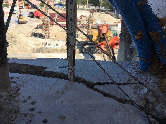
RE: The 2 photos posted.
I had not seen the left photo - am I correct in thinking that is the west side of member 11 and the tape measure is touching the top of the deck?
Both the member 11 in the right photo and the horizontal filler formed between 11 and 12 shown in the left photo are BURSTING. Not a good thing in a compression element, particularly when the stability of a 950 ton structure depends on that single member supporting that compression.
Judging by the exotic crack monitoring technique of an "X" across the crack, it appears the surface is ruptured outward also. Note the offsets visible in the lines. (What was the budget for construction inspection? We appreciate someone marking the "X" - it shows better in a photo than a glued on grid the size of a credit card.)
At the time the left photo was taken the failure was in progress, but the force in 11 was somehow being supported by the portion of the deck which blew out later.
I see the top of the fillet between 11 and 12 is 14", not the 15" called for on the drawings. MCM gets one demerit. It will be interesting to see how much a lawyer can charge to that variation.


Earth314159 said:
I can't see that the transportation did any damage that would significantly contributed to the failure mechanism.
That's what I though until I read the OHSA report which focused on it heavily and ran basic calcs.

Even with the PT stands member 11 was under tension and moment. A prime scenario for initiating cracks and weakening an already weak joint.
 
My rough calculations showed 11 to be in compression during support conditions during transport.
From Vance Wiley 24 Jun 19 04:35June ( member 11 was) " prestressed to about 560 kips, in the case of 11. The cantilever created about 250 kips tension in 11 so it remained under about 310 kips compression."
What did I miss?
EDIT I see I used the upper node dimension instead of the distance from 9/10 to 11/12 which I see is about 40 feet. 11 k/ft x 40/2 = 220 Kips. Diagonal = 220k/tan31.8 degrees =354 Kips tension. So compression remains = 560K - 354 k = about 200 kips compression.
EDIT 2 220 kips/sin 31.8 degrees = 420 kips. So 11 is under 560 - 420 = 140 kips compression.
Time for me to hang it up.


Vance Wiley said:
west side of member 11 and the tape measure is touching the top of the deck?
Yes, it is the west side of #11, but the tape measure is penetrating the deck by about an inch. ( see the inset at the top right in that left photo.)

SF Charlie
Eng-Tips.com Forum Policies
 
Vance Wiley (Structural) The cracking in #11 is part & partial of the cracking after detensioning.
 
Thank you. I have struck that part of my post. MCM recovers the demerit.
And I must adjust my screen settings. You had specifically indicated that penetration.
 
Vance Wiley said:
My rough calculations showed 11 to be in compression during support conditions during transport.
You are correct. I got my units mixed up in my quick calculation. I don't normally deal with kips. ;-)
 
The photo is from Fig 42 of OSHA report which also shows crack depth of 6" to 7" by Fig 39. The deck itself has crack depth of 3" and 4" according to Fig 31 and 30 too. The entire construction joint between 11/12 and the deck had slid.
 
Presumably the cracks were full depth? The diagonal cracks on the top surface are the same failure surface as the cracks on the back side of diaphragm II?

Because the cracks are jagged and change direction the straight tape measure only go so far in.
 
Tomfh,

Fig 29 of OSHA, enlarged below, is probably the most significant on the fate of 11/12 joint.

Screenshot_from_2019-06-25_01-01-42_ldjlac.png

Screenshot_from_2019-06-25_01-07-24_vn1ck3.png


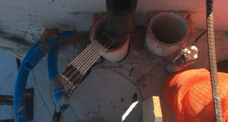
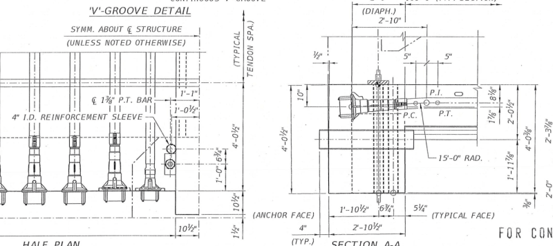
The centre line of north south 4" ID sleeve is only 5.25" from the north south face of the 2' wide Diaphragm II but has a 1" deep crack according to OSHA Fig 42. After passing the south north sleeve the deck had totally sheared off by about 5 to 10mm (say 5mm on either side of south north sleeve). Concrete has little area and hence little resistance/bond between the two sleeves.

Thus on Mar 13 the evidence in the field indicated 11/12 was departing from the deck with 5 to 10mm outward deflection and crack depths of 1", 3" and 4". The cracks traveled possible 45 degree downward and eventually took out a large prism of the south North face of the Diaphragm II as indicated by OSHA Fig 62. The shape of the prism was already visible by Fig 25 and 27 before the collapse.

The failure mode was as predicted by FDOT engineer Andres who marked up a drawing on Sep 15 2016 when FIGG was still developing the design. Despite FDOT's alert given 18 months in advance FIGG only managed to arrange the diagonal crack shorter by diverting it to the 11/12 face with the use of two pipe sleeves.
 
Human 909 said:
That's what I though until I read the OHSA report which focused on it heavily and ran basic calcs.

Even with the PT stands member 11 was under tension and moment. A prime scenario for initiating cracks and weakening an already weak joint.

The temporary PT force on #11 was higher than the diagonal tension force. The shear on the connection was reversed, much smaller in magnitude and directed towards the deck.

If the contractor had shored under the #9/#10 joint once the cracks opened up, it would have helped close the cracks.

For certain, it is something to calculate and check but I can't see it as a major contributing factor. I will go over the OSHA calcs on this issue to make sure I am not missing something (I can always be wrong and might find something new). The fundamental issue was the over stress of the shear friction in stage 3. Without this, you don't have a failure of the joint.
 
saikee said:
The failure mode was as predicted by FDOT engineer Andres who marked up a drawing on Sep 15 2016 when FIGG was still developing the design.

Yeah, a fairly clear prediction in those markups.

Where did those FDOT markup plans come from? Who released them?
 
earth said:
The fundamental issue was the over stress of the shear friction in stage 3. Without this, you don't have a failure of the joint.

You also wouldn't have had a failure if the back of diaphragm II didn't punch out.

The shear friction plane failed. The back of diaphragm II failed. All these things broke.
 
saikee119 (Structural)25 Jun 19 00:43 said:
The centre line of north 4" ID sleeve is only 5.25" from the north face of the 2' wide Diaphragm II
I comment here only for the sake of clarity, not to be critical. Your posts contain much pertinent information and are helpful.
I think your reference to north face and north pipe sleeve is influenced by the OSHA report which was misleading. I suspect their orientation was influenced by the position of the deck segment in their yard and not as it existed on the construction site.
OSHA has their north and south reversed as it applies to deck segment at 11/12.

 
Tomfh,

One thing stands out in this project is FDOT during previews of the submissions marked up FIGG drawings on arears of concern. I agreed with nearly all of them as the cracks were predicted at locations where stress changes abruptly. CBSNBS has done a timeline called "The path to FIU bridge disaster" and release the above information to the public.


Vance Wiley (Structural),

OSHA did not make the mistake. I made the mistake. Thanks for pointing out. I now had the north and south directions corrected in the post.


SFCharlie (Computer),


I agree OSHA Fig 30 shows the worst condition for the cracks. To me Fig 29 is more important because on its own I know the west side has gone and amount of movement can be estimated by the gaps around the north sleeve.

The bridge can have a small non-structural part broken off and still would not compromise the bridge's integrity. So Fig 30 on its own is not decisive until people notice the same pattern was being repeated on the east side with the same ferocity. Once 11/12 had serious 45 degree cracks on both sides the next concern is how much this most critical joint had moved.

OSHA Fig 30 is same as NTSB Fig 1. NTSB Fig 2 is also same as OSHA Fig 26 but taken at a different angle. The NTSB information, except Fig 3 which was used by OSHA as Fig 39, did not show how much 11/12 had moved. OSHA Fig 29 is the corroborating evidence on the 11/12 deflection movement. NTSB Fig 3 or OSHA Fig 35 is the confirmation 11/12 was separating from the deck at front or the last remaining side.

The seriousness of the cracks is that the already deflected structure is nearly impossible to repair.


Status
Not open for further replies.

Part and Inventory Search

Sponsor