Eng-Tips is the largest engineering community on the Internet

Intelligent Work Forums for Engineering Professionals

  • Congratulations waross on being selected by the Tek-Tips community for having the most helpful posts in the forums last week. Way to Go!

Miami Pedestrian Bridge, Part XI 32

Status
Not open for further replies.

JAE

Structural
Jun 27, 2000
15,432
0
36
US
A continuation of our discussion of this failure. Best to read the other threads first to avoid rehashing things already discussed.

Part I
thread815-436595

Part II
thread815-436699

Part III
thread815-436802

Part IV
thread815-436924

Part V
thread815-437029

Part VI
thread815-438451

Part VII
thread815-438966

Part VIII
thread815-440072

Part IX
thread815-451175

Part X
thread815-454618


Check out Eng-Tips Forum's Policies here:
faq731-376
 
Replies continue below

Recommended for you

I am laying bare the professional conducts of some of the parties in the bridge collapse to make the lawyers more difficult to cheat the public.

We all know it was the MCM subcontractor VSL's workmen who was the first party alarmed by the extent and severity of the cracks to the point they made a photographic record and showed them to the management. The inspection party BPA also participated in actively recording the cracks.

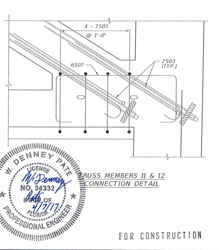
On Mar 15, 2018 three workmen from VSL, two from BPA and one from MCM were present in the re-tensioning work of Member 11. MikeW7's 23 Jun 19 01:38 post commented VSL employee Hanson kneeled twice to look at the 11/12 junction, the last time right before the collapse.

The Collapse - N view video does show this group of workmen stopped momentarily to examine the 11/12 joint several times, they needed to come down from the canopy, during the re-tensioning work. They were the only people really care about the bridge. Not being professional engineers able to diagnose the root cause of these cracks they nevertheless knew the cracks were extraordinary. I believe their interest was ensure no construction error from them to worsen the cracks.

We now know the MCM construction trailer nearby on that day was full of professional engineers who were better qualified to do the crack evaluation/assessment. Most of them were steamrollered to believe the cracks were not safety-related. The steamroller party even unilaterally gave an early instruction the to MCM that Member 11 were to be re-tensioned, without any repair now and obviously over the live traffic. The Mar 15,2018 meeting broke off at 11am according to FIU and CBSNBS investigation timeline reported that no one took steps to close the road while work proceeded on the cracking structure.

The real surprise to me is the re-tensioning work commenced approximately noon according to the OSHA report and so if any of the Mar 15, 2018 meeting attendees wishing to see the cracks and the result after the Member 11 was re-tensioned he/she could do so after leaving the meeting at 11am. None of the attendees did. The party who claimed the cracks were not a safety concern had no interest in seeing see the progress of the fatal work it instructed.

I would moderate the above by pointing out Contractually there were really two main parties in the FIU bridge; the owner and the consortium who designs and builds the required structure. The Owner is represented by BPA as according to the organization chart in OSHA report, BPA should be directly answerable to FIU and possibly viewed as Owner's Engineer or representative. BPA had two engineers present in the collapsed bridge and does have the Owner's power to stop the re-tensioning work if BPA deems it would be unsafe to allow traffic to go underneath. The least BPA could discharge its duty is formally to write to FIU the risk associated with the known cracks. BPA has to justify any action to stop work and face the massive claim by MCM. I am sure FIU would have within its establishment some professors able to provide a third party opinion to the cracking problem. This action should have taken place on Mar 13, 2018 after the cracks were fully photographed.

On the consortium side MCM was well represented by the subcontractor's workmen and one of its own staff. Nearly all contractors I know would position their position at the right contractual position when it come to any technical matter/decsion. In the next bridge MCM may be wise enough to stop work but in the FIU project MCM only concentrated on making sure every tensioning, de-tensioning and re-tensioning work was carried out as per the designer's instruction. MCM could be criticized for the lack of safety appreciation on the cracking bridge but on record MCM was disturbed unhappy with them in the correspondences. I also of the view that MCM can pay and obtain any third party professional opinion quickly to assist its private evaluation if MCM deems the matter were disturbing enough.

The designer was conspicuously missing in the remedial work instigated by him. It makes people wonder on what basis could he claim the distressed bridge wasn't a safety issue and could be so relax to manage everything remotely. On record the designer was the first one to conceive the FIU bridge but the last one to think it could collapse.

 
saikee119 (Structural)25 Jun 19 13:03 said:
MikeW7's 23 Jun 19 01:38 post commented VSL employee Hanson kneeled twice to look at the 11/12 junction, the last time right before the collapse.

I looked at the video again and noted more details - Video link set to start at 1:57
[ul]
[li]1:59 - Person talking with Hanson leaves. I wonder who this is?[/li]
[li]2:01 - Hanson begins continuously monitoring 11-12. Is this when tensioning begins?[/li]
[/ul]

I went thru the video frame-by-frame and compiled a lengthy list of events, then lost the edit. Grrrrrr.......
 
The order to de-tension and then re-tension the rods in #11 shows how completely confused the design team was. These rods could add and/or subtract ZERO force to the region of failure, which was outside of the #11 envelope. The rods would have had no effect on the failure mode whatsoever. What caused the failure was a total absence of any steel tying #11 to the deck.
 
There have been criticisms leveled at FIU for doing nothing. I think FIU/BPA should come clean on this one.

I said this because OSHA sourced 21 out of the 23 photos on the cracks photographed on Mar 13 from BPA. Thus BPA had to be party with the most information on the cracks. Did BPA shared these photos and concerns fully with the others?

BPA was selected by FIU and so it had to communicate with FIU first on the seriousness of the cracks before jointly seeking a solution from the Design and Build Consortium. Thus BPA had to have a view and more importantly a criterion on how the cracks could be fixed. After all BPA would at the end has on behalf of FIU to inspect the repaired bridge and recommend acceptance or rejection.

May be I am naive because if FIU/BPA were unsure of the crack severity there is nothing to stop them from picking a telephone to summon an army of free experts from the University payroll to offer quickly a third party opinion. My expectation from the experienced academics is the majority would not accept the risk of carrying out re-tensioning on a badly cracked critical Member 11 while the live traffic passing underneath. Thus I believe FIU/BPA could have done a lot more to control the situation or even avert the disaster. If FIU were so readily to believe what the bridge designer said it should have saved money not to hire BPA. BPA was hired to protect FIU's interest on the technical acceptance of the work so has BPA failed its duty?
 
FortyYearsExperience (Structural) said:
What caused the failure was a total absence of any steel tying #11 to the deck.

OSHA Fig 61, 62, 64 to 70 show bars left in the deck when 11/12 was pulled out by the falling action of the deck. Thus you may like to replace "any steel" with "sufficient effective steel" in your post. OSHA does condemn some steel bar ineffective as they failed to comply with the code on development length.

Also the sketch below shows at least 4 shear links intercept the construction joint.

Screenshot_from_2019-03-30_22-21-46_dwqaqo.png


OSHA Fig 63 has hints the above links had sheared across the construction joint

On whether the PT rods effect on the failure mode OSHA Fig 19 and Fig 30 show the same crack when the Member 11 was first tensioned and de-pensioned respectively. The crack of Fig 39 was 7" deep and serves as strong evidence that the one rod was effective in pulling the deck while the order was 11/12 and split Member 11 at the bottom end. It was the action of the PT rods that first damaged the joint and later triggered the collapse. To suggest the PT rods to have no effect on the failure mode will require challenging proof. The historical development of the cracks has already proved beyond doubt the construction sheared and cracked as soon as PT tension was first introduced.
 
[b said:
FortyYearsExperience]and saikee119[/b]
I would like to have seen member 11 and the deck connected through a "strut and tie" method with the reinforcing of 11 lapping and transferring the thrust to an imaginary "strut" within the deck with the capacity to handle all the horizontal component from the load in 11 and extending maybe 40 feet toward the center of this span. That would have required maybe two tons of reinforcing and cost maybe ten grand.
I think this would have satisfied the concerns that have been expressed by FortyYearsExperience earlier in this forum and with which I agree.
I also question the wisdom of a sloping (forcewise) construction joint in a member of the importance of 11 and with loads of this magnitude. Creating a square face on the joint at 11 and deck would have avoided the shear friction issue. It would have required a formed "socket" in the deck, perhaps, with more concrete below the deck and with proper reinforcing around that "socket" but it may have provided a more predictable transfer of the forces from 11 to the deck.
Also there should have been dedicated confinement reinforcing in members like 11, as well as at all nodes of the truss.
 
For the first time I have discovered what has bothering me about the detailing of node 11/12 and deck, as shown in your referenced post. At least two things, there are more remaining.
First, the 4 - #7 hoops designated "7S01". The bottom cross leg of those hoops is shown to pass through the formed channel for the drain pipe below the deck. Am I not correct in thinking these are closed ties? This would have been sorted out during the placing of reinforcing, I am sure. Regarding same 7S01 hoops, the one in the fillet between 11 and the deck explains why that small fillet stuck to the deck in the early cracking of this joint. The fillet was anchored by the southmost hoop.
 
Vance Wiley (Structural)25 Jun 19 17:39 said:
The bottom cross leg of those hoops is shown to pass through the formed channel for the drain pipe below the deck. Am I not correct in thinking these are closed ties?
I admit it is hard to tell from the cropped drawing , but the drainpipe is outside the bottom of the deck in a channel.
figg_signed_deck_end_view_rebar_h6mlq3.jpg


SF Charlie
Eng-Tips.com Forum Policies
 
saikee119 (Structural) - The Timeline was created by NBC not CBS.

For the record, Structural Technologies, a subsidiary of Structural Group was the subcontractor responsible for all the formwork, reinforcement & place & finish. VSL, a subsidiary of Structural Group was the PT subcontractor. MCM seems to have been mostly construction management.

I've been exploring the TiO2 issue with respect to the pristine rebar. Even the corrugated PT sleeves came away without even tiny scabs of concrete attached. There doesn't appear to be research regarding the bond strength of TiO2 modified concrete to rebar. There is a lot of positive research about nano-TiO2 and a resulting increase in strength. This seems to be the case with many "nano" constituents. Wonder of wonders, filling in the empty spaces between the sand, cement & aggregate makes concrete more solid.

The "Environmental" hype about TiO2 and NO2 conversion to an NO dust & subsequent "self-cleaning" has me wondering about how TiO2 may be modifying the surface energy of concrete. Epoxies have a surface energy of 35 to 45 dynes/cm. Based on the information I can find, TiO2 has about the same surface energy as epoxies. The thing about surface modification is that sometimes it doesn't take much of an ingredient to completely change the performance of a mixture. Epoxy coated rebar require greater development length. Maybe there needs to be some research done to determine if the addition of TiO2 isn't affecting rebar strength development.
 
A diamond is pretty solid - and shatters easily. I wonder if the introduction of TiO2 is reducing the ability of the concrete to accommodate strains?
A new industry on the future - using TiO2 to clean used rebar. All the visible rebar appears to be a lot cleaner than I expected. No adhesion?
Did the TiO2 affect or totally defeat "cohesion " in the cold joint? Seems possible as a side effect or unintended consequence, considering it reacts with things that contact it and paints itself white (grows a white coating). Should cohesion be a no-no if TiO2 is used? Development lengths increased as you suggest?
I have mentioned before how brittle the concrete seems to appear. What is the elasticity?
This may bring a rich chemical company into the nest of defendants.
"Surface Energy" - I have encountered that term. Perhaps you could provide an explanation of how it works and might apply in this case?


epoxybot (Structural) 25 Jun 19 20:04 said:
I've been exploring the TiO2 issue ...

Is it clear if "plain" Ti02 was used, or NT (nanotitanium)? Here's some info on both on pages 34-35 of this research paper (end page dated 2017):
To be effective, the nanotitanium needs to be at the ‘interface’ of the concrete, i.e. at the point where it can react with sunlight and organic debris (which then breaks down to CO2 and water). For this reason, and also to reduce cost, it is more usefully added as a surface coating or thin slurry rather than being mixed into construction concrete.
It also says
Titanium dioxide is also photocatalytic in its non-nano form which is considerably cheaper than nanotitanium, and potentially less toxic. This may explain why the use of nanotitanium in concrete is currently extremely limited.

In either case, it appears there is no practical reason to incorporate Ti02 or NT into the concrete-rebar interfaces, so is it known if the TiO2/NT was used merely as a topcoat? I remember several comments about a "white slurry".

ADD: If it's expensive and used primarily as a topcoat, that would explain why there's no literature about its effect on rebar, etc.
 
Titanium additive -
A surface treatment makes sense. Did they paint the diagonals white or is that a Titanium coating that has (had) already reacted? Is it to be sprayed on or surface applied to the bottom of the canopy and deck?
 
The diagonals look like they received a parging of additional TiO2 surface coating but integral TiO2 was called for in the design.

TiO2_1_svlxej.jpg


TiO2_2_pp1pf3.jpg


Surface energy is probably best understood by the contact angle of water on a given surface. Water being a liquid with a very high surface tension @ 72 dyne/cm.

Surface-Energy-Chart_p6j64n.png
 
epoxybot (Structural) 25 Jun 19 21:12 - So adding Titanium to the concrete mix increases the cost by a factor of 2.5 to 3.2, yet it has no known benefit. Hmmm.... And there also doesn't appear to be any literature explaining how concrete properties are affected by its addition. (...cricket noises...)

EDIT: I'm referring to my post of 25 Jun 19 20:48 which explains that TiO2 only has useful properties when it's used as a surface coating.
 
For those who were surprised to find the rebar, left behind after the collapse, were so clean with little or no concrete fragments attached it would be useful to remind ourselves that when the 11/12 joint failed the deck dropped to the ground but the 11/12 was caught by the pier. Therefore there would have been some heavy tensile forces by the dropping deck to pull itself out of 11/12.

Thus the 11/12 failure mode might have be a horizontal shear failure to start with but the dropping action of the deck would have led to a blow out of the joint when a large number of rebar did not have the adequate development length or the concrete surrounding the rebar was simply inadequate for the embedment purpose. It goes without saying the rebar next to the four vertical sleeves had the least chance of being gripped firmly by the concrete.
 
Vance said:
I would like to have seen member 11 and the deck connected through a "strut and tie" method with the reinforcing of 11 lapping and transferring the thrust to an imaginary "strut" within the deck with the capacity to handle all the horizontal component from the load in 11 and extending maybe 40 feet toward the center of this span.

Yes.

A thickening of diaphragm II would have been good too (to reduce punching shear stress), or it that was deemed unsightly a massive steel plate on the end of diaphragm II with welded bars reaching back a long way back into the deck.


Vance said:
I also question the wisdom of a sloping (forcewise) construction joint in a member of the importance of 11 and with loads of this magnitude. Creating a square face on the joint at 11 and deck would have avoided the shear friction issue

Yes with the benefit of hindsight it was a bad idea to align the construction joint with the shearing force. It should have been rotated to the compressive stress direction, with a socket or a stub.

I still don’t know if the shear friction would be ok though. The bridge could still shear at that junction.
 
UH-OH.
From an earlier post - "Don't be the first guy to try something and don't be the last guy to use something".
FIGG may have hit a double. First AND Last.
 
Status
Not open for further replies.
Back
Top