Continue to Site

Eng-Tips is the largest engineering community on the Internet

Intelligent Work Forums for Engineering Professionals

  • Congratulations GregLocock on being selected by the Eng-Tips community for having the most helpful posts in the forums last week. Way to Go!

Miami Pedestrian Bridge, Part XI 32

Status
Not open for further replies.

JAE

Structural
Jun 27, 2000
15,463
A continuation of our discussion of this failure. Best to read the other threads first to avoid rehashing things already discussed.

Part I
thread815-436595

Part II
thread815-436699

Part III
thread815-436802

Part IV
thread815-436924

Part V
thread815-437029

Part VI
thread815-438451

Part VII
thread815-438966

Part VIII
thread815-440072

Part IX
thread815-451175

Part X
thread815-454618


Check out Eng-Tips Forum's Policies here:
faq731-376
 
Replies continue below

Recommended for you


saikee119 Would the bridge still stand today if the de-tension operation were omitted?
 

It is basically impossible to predict when a compromised structure will collapse, but it is possible it would still stand. I think there is a very low likelihood, however.
Stressing was to proceed by ( 1) partial stressing the deck, D1 tendons only,
( 2 ) partially stressing canopy , and ( 3 ) Stressing 2 and 11 (in anticipation of the end bays cantilevering during transport).
While supported by the transporters at the first interior bottom panel points 3/4 and 9/10, members 2 and 11 were in tension so they were prestressed to about 560 kips, in the case of 11. The cantilever created about 250 kips tension in 11 so it remained under about 310 kips compression.
The self weight force in 11 when spanning the full 174 feet has been presented as 1300 kips compression, and I agree with that approximate load. Live load will create about 0.25 X 1300 = 325 kips. So the combination of PT force (530 kips) and self weight (1300 kips) exceeds the anticipated Total Load (unfactored - the “real” load) by about 200 kips. Without consideration for (or knowledge of) damage to node 11/12 it was appropriate to remove the PT forces in 11 when the weight of the structure was transferred onto the pylon and south support.
As I understand things, cracking was observed at node 11/12 just after the PT forces were removed. Because the 560 kip PT force was internal to member 11 it loaded that member unnecessarily. And the angle of 11 was 31.8 degrees (less than 45 degrees) so the PT caused more force thru the cold joint than it provided perpendicular clamping force. But ( my current thought is) apparently the compression under the anchor plates at the 11/12 end also provided confinement to the concrete in that zone, which was providing unexpected resistance - assisting the “R” in LRFD.
I pose for consideration that the unexpected resistance was anchoring the lower zones of what became the break out failure mode.
The deck level portion of the final failure plane had slipped earlier, and without the backup of the lower zones presumably mobilized by the compression under the PT anchor plates the failure progressed in an increasingly dramatic manner.
The “shear friction” resistance of the cold joint was not uniform across the contact plane. This allowed incremental failure of the different zones, with the demand increasing on those remaining zones. Releasing the PT in 11 likely allowed this failure mode.
Maintaining the PT forces in 11 was not intended and would likely have masked what was a very questionable connection. Maintaining the PT force might have allowed time for remedial work, but without additional support that work would have been performed at great risk.
In short, I am amazed that a firm with the record of FIGG experienced this problem we see in 11 and the 11/12 node. I am astounded that they could not see a failure in progress and imminent.
 

Vance Wiley (Structural)


We all know the tension in 11 was temporary and had no use once the span had been installed at its final position.

I used the proposal to highlight the facts :

(1) The de-tensioning of 11 damaged connection beyond repair. (strengthening modification would be required if the connection were to be rebuilt)

(2) The re-tensioning of 11 pushed the bridge to collapse. (proved to be a bad choice to cure the cracks)

I like to know why doing something harmless (to reduce the compression in 11 by removing the PT rod tension) could damage the structure so seriously. And then restoring the bridge to its previous condition could kill it.
 
jrs_87 (Mechanical) said:
Question, was omitting sleeves and drain pipe from solid model at node and diaphragm trivial for FEA? In FIGG's presentation I see a large stress concentration in the vicinity of the drain pipe. The drain pipe passage was omitted from the model.

For those interested about chains used in move. I found documents that instructed movers to tighten chains before horizontal motion and slacken them before lifting and lowering structure. Also, they were not allowed to dip east or west more then 1/4 inch. They did not achieve that goal.

What was the purpose of the pipes attached directly to diaphragm II while it was in the casting yard? Were they to prevent rotation from PT forces?

(1) Omitting the sleeves and drain pipe for FEA is due the complication they introduced making the analysis extremely costly. There is no money in a footbridge budget to go that far.

(2) Damage inflicted during the SPMT transfer could be difficult to control and quantify. Knowing what we know now the contractor should have photographed every crack in the structure before proceeding to de-tensioning.

(3) I believe there were small flexible black pipe/hose installed for grouting the PT duct interior. One can see it in some OSHA photos.
 
Saikee said:
I like to know why doing something harmless (to reduce the compression in 11 by removing the PT rod tension) could damage the structure so seriously. And then restoring the bridge to its previous condition could kill it.

It’s something I’ll be mindful of in future. Tensioning and detensioning are not necessarily reversible. It can be one way, with no going back.
 
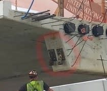
These are mounts for the formwork props (pipes) I was referring to. These props were mentioned in OSHA report.

s
InkedFIU-bridge-beforehand_LI_nzstlv.jpg
 
saikee119 said:
I like to know why doing something harmless (to reduce the compression in 11 by removing the PT rod tension) could damage the structure so seriously. And then restoring the bridge to its previous condition could kill it
Because it wasn't harmless. Removing the PT rod tension changes the stress distribution which if it causes cracks then those cracks to glue themselves back together when you attempt to add compression and return the structure to its previous state. The previous state could no longer be achieved as cracks had formed and grown.

Lets not forget that there is significant moment being transferred through those truss members.
 
human909 (Structural)24 Jun 19 11:28

Would it be reasonable to suspect the moment at 11/12 was the most highly concentrated moment in structure? This thing was not really a truss because trusses don't transmit moments. Someways it was a (thin web) I-beam with hidden shear lag. < Just ideas, I don't know.

 
jrs_87 said:
Would it be reasonable to suspect the moment at 11/12 was the most highly concentrated moment in structure? This thing was not really a truss because trusses don't transmit moments. Someways it was a (thin web) I-beam with hidden shear lag. < Just ideas, I don't know.

I see a problem with calling it a truss. If we chose to be that pedantic then most trusses aren't trusses. Most connections transfer some moment. Throw it into your favourite structural modelling software and you can get and VAGUE idea about the forces in the uncracked structure. That truss member has significant moment AND the vertical member 12 has a very significant moment caused by the roof. This moment again tries to kick out the bottom of member 12 all while 11 is also trying to punch it horizontally.

But really this is still kids playing in the sandpit stuff. I think there has better discussion in the pages previously and in the OSHA report. All simple modelling does is help display approximately the nature of the forces its the connections design and potentially the reverse cantilever load during the move that are the critical aspects.
 
jrs_87 (Mechanical) said:
Would it be reasonable to suspect the moment at 11/12 was the most highly concentrated moment in structure? This thing was not really a truss because trusses don't transmit moments. Someways it was a (thin web) I-beam with hidden shear lag. < Just ideas, I don't know.

In Moment distribution method by hand, if one has done it in University and still remember it, the moment at a joint is distributed according to the ratio of their stiffness or the "I-value" or the second moments of area.

Member 12 has the largest I-value in the joint of 11/12 with the deck as it is the deepest (I-value is governed by the height to the power of 3). The deck is a lot thinner and its effective breadth is likely to be a limited width permitted by the design code.

Moment exists because the joint was made rigid. The truss the students analyse in their early years has pinned connections to simplify the calculation to just axial forces and shear. In a real structure people make the joint rigid because it is cheaper and structurally stronger. There are moments in 11/12 but I would say the axial forces and shears should be dominant.
 
jrs_87 (Mechanical) said:
These are mounts for the formwork props (pipes) I was referring to. These props were mentioned in OSHA report.

If it was OSHA report Page 32 you were referring to my interpretation is four hard bearing pads are the standard bridge bearings. The drawings signed for construction show 2 bearing per diaphragm but one construction photo does show 4 bearings.

Screenshot_from_2019-06-24_14-56-38_k2jipe.png


The B46 and B47 official construction drawings show no side attachments so I tend to regard them as temporary work to be removed after completion.

The attachments pointed out by you cannot be bearings because in the final position there is no concrete support underneath them as depicted by this photo.

Screenshot_from_2019-06-24_14-53-32_ci87zw.png
 
saikee119 (Structural) 24 Jun 19 14:01 said:
The drawings signed for construction show 2 bearing per diaphragm
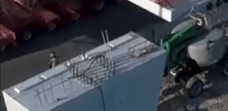
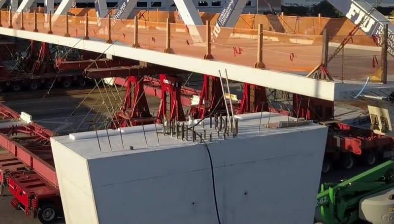
Here are some cropped images taken from the DROPBOX drone footage:

DJI_0013.mp4 at 00:59 (your image was taken from the same video, at a later time)
DJI_0013.mp4_snapshot_00_59_cropped_dst4x1.jpg


DJI_0014.mp4 @ 01:10
DJI_0014.mp4_snapshot_01_10_cropped_tjvrev.jpg
 
Saikee119 said:
Omitting the sleeves and drain pipe for FEA is due the complication they introduced making the analysis extremely costly. There is no money in a footbridge budget to go that far.
Modeling the drain pipe should not have been expensive. Modern modeling software allows one to "subtract" a solid from an existing model. specify a cylinder (the pipe) and subtract it. Of course, they may not have had modern software?
 
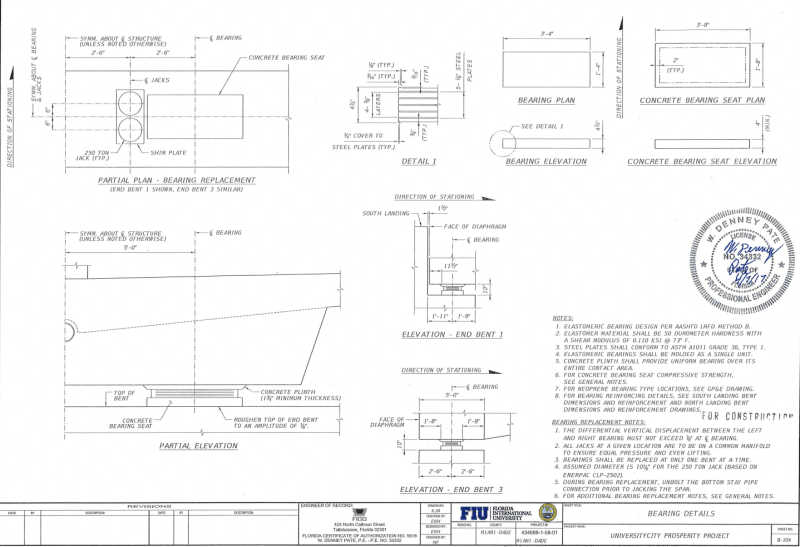
I could only find one drawing below showing bearing details.

Screenshot_from_2019-06-24_16-02-29_tjrc40.png


MikeW7 photos seem to suggest the bearing arrangement was different between the span's two ends. The above drawing has no information on Bent2. Looks like Bent1 is the south end of the doomed span, Bent2 the midpoint the doomed span meets the back span and Bent3 the north end of back span.
 
Dumb question about pads on the north pier: Shouldn't the canal span also sit on pads? In the picture I posted there doesn't appear to be room for pads because of the vertical rebar.
 
(1) The de-tensioning of 11 damaged connection beyond repair. (strengthening modification would be required if the connection were to be rebuilt)

There are arguments for the "beyond repair" part. That joint shows significant damage in photo 4 well before the PT rods were de-tensioned. Is it actually practical to repair that area of the bridge with it overhead? That would likely require shoring the bridge and de-tensioning the end of the deck and 11/12 members could be completely rebuilt. So, could the issue even be repaired? I'm suspect the experts would say no, it's not possible. Don't forget, the other end likely had the same issue and would also need a similar re-built to also build it right.

You seem to be pushing the opinion that it was properly constructed but either the tensioning in 11 or the move broke it. I doubt there are many others who share that view.


I like to know why doing something harmless (to reduce the compression in 11 by removing the PT rod tension) could damage the structure so seriously. And then restoring the bridge to its previous condition could kill it.


The de-tensioning wasn't harmless, but that's because the structure had design issues and changing the forces let those design issues behave differently. Overall, I would bet that a similar failure would have eventually occurred even if the PT rods in 11 were left tensioned. The joint was failing from the start, the speed just increased once the tension was released.

As for your second point - the joint started to fail and the releasing of the PT rods let the failure progress much further. It should be rather obvious that re-tensioning the rods can't undo the damage in the joint.


LionelHutz (Electrical),

From concrete repairs experience as someone who had to design the remedial schemes, write the specification, specify/approve the materials, select contractor/suppliers, provide procedure for the execution/implementation, supervise the repair and finally certify completion I will not be able to guarantee my work if the repair done to 100% of the original but still produce the same defects which are shear cracks in this case.

Thus my definition of a strengthening scheme is to modify the structure to cure the defects. Such strengthening scheme will have to be based on theoretical calculations after the root cause has been correctly identified.

If the work has been constructed properly but failed it could also be due to a deficient in design. OSHA has already pointed out some installed rebar were ineffective in resisting shear as they did not meet the code requirements. The structural arrangement of the failed 11/12 joint is vital. All plastic sleeves remain in place. Were they stronger than concrete that broke off first? Many rebar remained with little distortion when the surrounding concrete disappeared. Were they useless in resisting load?

Whatever has been arranged between 11/12 and the deck leads to damage if it were de-tensioned and re-tensioning it back kills the bridge. This is based on historical evidence. My language is just to focus readers' attention.
 
MikeW7 (Electrical) said:
Dumb question about pads on the north pier: Shouldn't the canal span also sit on pads? In the picture I posted there doesn't appear to be room for pads because of the vertical rebar.

Not a dumb question. We just have no information on the north end arrangement.

As an idiot trying not to be one I would say it is unwise to slide the bridge bottom on the bare concrete north pier and to drop a thin layer of something hard and noncorrosive would be ideal. A proper bearing, allowing the standard horizontal bridge movements, has already been specified at the south pier.

OSHA report has the following references:

"The diaphragm sat over the bearings consisting of four hard plastic pads."

"FIGG asked MCM at around 9:45 am to put an additional plastic shim “right away” similar to the existing shims on the pylon directly under the diaphragm."
after large cracks were discovered in 11/12 on Mar 13, 2018.
 
jrs_87(Mechanical)24 Jun 19 01:42 said:
For those interested about chains used in move. I found documents that instructed movers to tighten chains before horizontal motion and slacken them before lifting and lowering structure.

I started working on a clearer explanation of the chains a couple of days ago, and I will use your comment as a convient starting point.

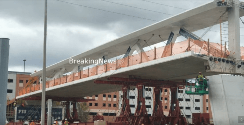
OVERVIEW: From what I can piece together from several videos:
[ul]
[li]The spiderweb of tower-to-base chains were tightened at the casting yard and never loosened until the bridge was just west of the piers.[/li]
[li]Before the bridge was moved over the piers the tower-to-base chains were removed, the bridge raised and leveled, and the chains reattached.[/li]
[li]The chains remained in place until the bridge was squared up in the E-W and N-S directions over the piers, ready to drop into place.[/li]
[/ul]

DETAILS:

There appear to be 3 separate chain groups, each with a different purpose:
[ol 1]
[li]Both canopy ends are chained to the deck curbs to prevent the canopy from rocking side-to-side. (my assumption)[/li]
[li]The canopy above each SPMT group is chained to the arms of the SPMT towers to hold the bridge against cribbing on top of the towers. (my assumption)[/li]
[li]The largest group of chains connect the SPMT tower tops to the mover bases and spreader bars. My guess is that these chains act as a stop so the SPMT towers can be raised until all the slack is out of the chains, causing each tower to become a rigid extension of its base.[/li]
[/ol]

The group 3 chains remained tight during the move. As the SPMTs traverse the road median at the 00:59 mark of the Move Part 2 - ground view video you can see each wheel raise and lower as is passes over the median, but the tower chains are never relaxed.

When the bridge is moved into position just west of the piers, several incremental adjustments are made, as shown in the Move part 3 - SW view video. Open the video in a separate window so you can follow along:
[ul]
[li]00:10 - Starting at the north end, jacks on the wheel trucks of the SPMT bases are individually lowered and raised to adjust the east-west and north-south tilt of the bridge. The presence of these jacks is my assumption, but some mechanism is clearly elevating the SPMT bases at ground level.[/li]
[li]00:20 - The group 3 chains are removed.[/li]
[li]00:25 - The SPMT towers are raised so the bridge will clear the piers, and to level the bridge north-south.[/li]
[li]00:41 - The group 3 chains are reattached.[/li]
[li]00:56 - The bridge is moved over the piers.[/li]
[/ul]

Once the bridge is over the piers, more adjustments are made, as shown in the Move Part 3 - ground view east 2 video:
[ul]
[li]00:39 - The SPMT wheel trucks are used to turn the bridge, and crab it sideways.[/li]
[li]01:31 - The SPMT Towers are lowered slightly, causing slack in the group 3 chains. As far as I can tell, the bridge wasn't completely lowered onto the piers during this phase, because the group 2 chains would collapse the canopy if weight is taken off the SPMT cribbing.[/li]
[li]01:35 - The SPMT towers are used to make final tilt adjustments.[/li]
[/ul]

Before the bridge is lowered onto the piers, workers remove the Group 1&2 chains, as shown at the 16:47 mark of the Move Part 3 - SE view video.

The chain removal, final positioning, and SPMT withdrawal can be watched starting at the 01:22 mark of the Move Part 3 - SW view video.
 
saikee119 (Structural)24 Jun 19 10:46 I like to know why doing something harmless (to reduce the compression in 11 by removing the PT rod tension) could damage the structure so seriously. And then restoring the bridge to its previous condition could kill it.
In my mind member 11 and node/joint 11/12 to deck were seriously under capacity , particularly in the stand-alone condition of March 15. Movements in the joint were apparently slight prior to transport and de-tensioning.
Releasing the PT was not harmless, IMO, because it relaxed internal stresses in the zones just ahead of the PT anchor plates, allowing some strain and deformation from the now first time 1300 kips member 11 was loaded with.
So there was some mis-alignment due to cracking, resulting in loss of interlock of previously homogeneous concrete, and after the cracking had progressed to a visibly recognized failure in progress, the PT was restored. The misalignment of pieces was not restored because the movement had been too great, and internal grinding and crushing was the result. This did not restore the joint to its previous condition.
At this point, the joint has completely failed, and collapse is underway.
Had there been time to restore the support of the transporter (or otherwise provided support), epoxy repairs could have been considered.
 
Assuming the posting by FIU of the documentation on their website of the Contracts, Plans, etc., was because of a FOIA request; I'm sure I'm not the only one wondering why the RFI's were not published. The RFC plans do mention Shims for the pylon but there isn't any mention of sizing or locations. The base of the north pylon was to grouted shortly after it was set, subsequent to grouting of the vertical PT bars for 12.

Absent from the Stage 3 sequence was detensioning of 11 & when it should occur in relation to the grouting procedures.

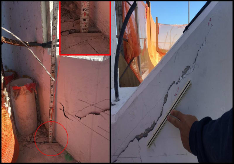
I just don't understand how Denny Pate or any engineer or VSL could consider introducing PT forces into member 11 when it was damaged. Not without first conducting some NDT.

Member_11_rt4amy.jpg


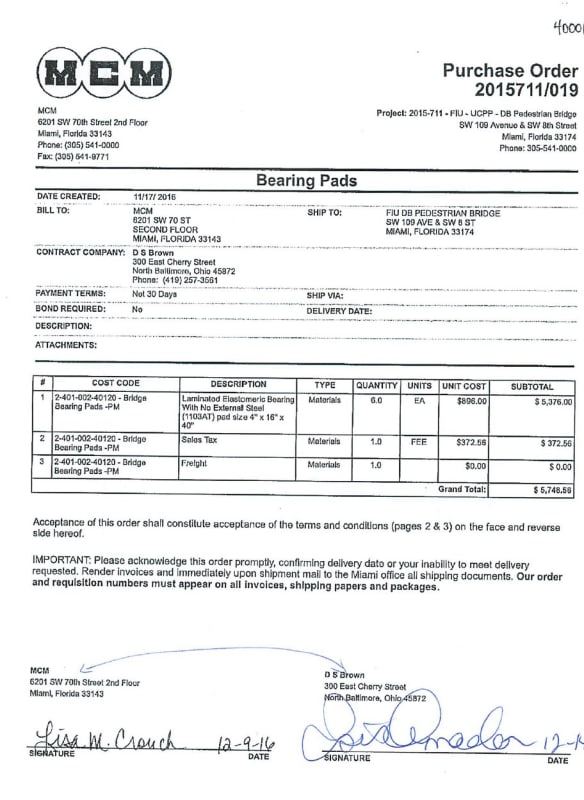
Information on the Bearing Pads. They probably had about a 50% horizontal displacement/accommodation.

Bearing_Pads_xgkcbx.jpg


Laminated_Bearing_Pads_d0l6ld.jpg
 
Status
Not open for further replies.

Part and Inventory Search

Sponsor