Eng-Tips is the largest engineering community on the Internet

Intelligent Work Forums for Engineering Professionals

  • Congratulations waross on being selected by the Tek-Tips community for having the most helpful posts in the forums last week. Way to Go!

Miami Pedestrian Bridge, Part XI 32

Status
Not open for further replies.

JAE

Structural
Jun 27, 2000
15,432
0
36
US
A continuation of our discussion of this failure. Best to read the other threads first to avoid rehashing things already discussed.

Part I
thread815-436595

Part II
thread815-436699

Part III
thread815-436802

Part IV
thread815-436924

Part V
thread815-437029

Part VI
thread815-438451

Part VII
thread815-438966

Part VIII
thread815-440072

Part IX
thread815-451175

Part X
thread815-454618


Check out Eng-Tips Forum's Policies here:
faq731-376
 
Replies continue below

Recommended for you

jrs_87 (Mechanical),

Isambard Kingdom Brunel said:
“Any idiot can build a bridge that stands, but it takes an engineer to build a bridge that barely stands.”

I am British trained and am pretty sure in Brunel's era engineers used only the elastic theory in the design which is safer with a larger margin of safety factors.

In today's design the envelope has been pushed forward by designing structures at ultimate limit state of collapse with working conditions adequately protected by commonly agreed safety factors stipulated by the codes and national standards. These safety factors change very little between countries.

A Designer is not allowed to build a bridge that barely stands. FDOT and Louis Berger are the authorities stopping it from happening in this project.

So if this bridge design does not have the relevant safety factors it is a non-compliant design and not one with a design error. I believe the former is illegal and so a criminal offence whereas the latter is a negligence.
 
jrs_87 said:
A Designer is not allowed to build a bridge that barely stands. FDOT and Louis Berger are the authorities stopping it from happening in this project.
I think you miss the point of the statement, well at least I interpret the statement vastly differently.

Throw enough stone, timber, steel or concrete at a structure and you don't need to be an engineer to make it stand up. You just need a decent budget and a little experience. Do you think the Romans and Greeks or Egyptians were calculating shear and moment capacity of their materials and structures? Sure some builders would have made mistakes in building bridges, aqueducts or amphitheatres but they fell down and they rebuilt with mateThrial so it would stand up.

The point is it takes an engineer to design a structure efficiently so it is 'just' strong enough for the required loads and very little more.

jrs_87 said:
In today's design the envelope has been pushed forward by designing structures at ultimate limit state of collapse with working conditions adequately protected by commonly agreed safety factors stipulated by the codes and national standards. These safety factors change very little between countries.
Ultimate limit design highlights this point completely, in fact the clue is in the name! Codes generally require a structure to be strong enough that it "barely stands" under extreme conditions and allowing for variation in material properties. There is no explicit safety factor in ultimate limit state design.

As per:
In the purest sense, it is now considered inappropriate to discuss safety factors when working with LSD, as there are concerns that this may lead to confusion.

While you may interpret various load factors and capacity reduction factors as safety factors that is not what they are intended to be. While this made seem like pedantry, it underlines the entire difference in philosophy of limit state design vs other methods that explicitly use factors of safety.


To put it another way. A FOS approach is almost like saying I don't know enough so I'll just throw a big factor on top to allow myself to sleep at night. A limit state approach says, I know the properties of my structure and I have very good idea of the loads and environmental loads it could likely experience. I can sleep at night if my design capacity is slightly bigger that my design loads. (For me 'slightly bigger' could mean 10% or 20% if I have tightly calculated design loads that lets me sleep at night just fine.)
 
I’ve always found the distinction between limit state strength design and factor of safety design to be rather artificial.

At the end of the day all the fancy limit state factors boil down to a safety factor very similar to traditional approach.

 
human909 (Structural),
It is no point going over "barely stands" because each one is entitled to his/her own interpretation.

Regarding the older civilisations building structures without our modern codes my explanation would be they didn't do tension and bending but relied on compression mainly. Ancient massive structures stand today but they are no longer affordable nowadays for what they serve.

In limit state design the safety factor is based on statistics. There is a lot human still do not know but a characteristic strength of steel or concrete is both based on a population of 5% could fail. Every country uses this criterion.

The safety factors on loading are based on good engineering practice. Naturally occurring loads like wind, earthquake, storm, rain, tides etc are based on return periods like one in a 100 years. On tides we use the HAT or Highest Astronomical Tide of the project site plus surge added on top if necessary.

A designer is always given the freedom to select any factor above what the design code mandates as long as he/she can justify it. If one is uncertain one would increase the safety factors to allow for the unknowns. The safety is always in the hand of the designer.

Therefore if a designer loses sleep at night it is mostly likely he/she has identified some uncertainties but hasn't raise the mandatory factors enough to cover the risks.

 
Tomfh (Structural) said:
I’ve always found the distinction between limit state strength design and factor of safety design to be rather artificial.

At the end of the day all the fancy limit state factors boil down to a safety factor very similar to traditional approach.

I must be very old as I went through the elastic design, Load factor design and the limit state design. I can explain the difference as below.

In elastic design, also referred to as the "Modular Ratio method", we design a structure in working condition (load factor=1) by restricting its maximum stresses of steel and concrete to within prescribed permissible limits. In this method we have no idea of and no interest in when the structure would fail.

To save a bit of money people changed the above to "Load factor method". In computation it is essentially the same elastic theory but the prescribed permissible concrete stress is based on a safety factor, with consideration on designed or nominal concrete mix, applied to the specified concrete strength. This is an attempt to estimate more closely the concrete resistance near the failure condition.

The Limit state design is different because for the first time the design is based on concrete at failure with a declared compressive strain of 0.003 (0.0035 in UK and EU). Both the American and UK/EU codes have partial safety factors for load as well as on materials. UK/EU codes have one partial safety factor for steel and another factor for concrete but American uses just one strength reduction factor to represent both concrete and steel. The American strength reduction factor can also change with stress types.

Based on my 30 years work on the analysis of concrete sections subjected to axial load and biaxial bending I can say the elastic theory and Limit State designs give nearly same result. This is because in LSD we design a section at the ultimate limit state of collapse but in its serviceability state or working condition the steel and concrete are mostly still inside elastic range. In UK/EU serviceability limit state the load factors are removed and partial safety factors, in concrete and steel, are adjusted lower according to the codes.

The above makes sense because most of our structures in normal working state (limit state of serviceability) should have the concrete and steel stresses still inside the elastic range. Thus we increased the volume of RC design computation possibly by 3 to 5 times to get back to where we started with the elastic theory.
 
Designing structures to Codes is risky at best in many cases. Preparing a design that satisfies code requirements will get your project approved by government agencies and may provide some protection in a court of law, but the engineering comes into play when one recognizes the critical members and joints and wisely puts a bit more there "for the wife and kiddies".
Also the needs of a certain project may far exceed the "minimum code requirements".
This 14 million dollar project needed about $10,000 - maybe $20,000 more steel and concrete in 11 and its joint to the deck. It is never cheaper than before the bid.
I see several things that illustrate an oversight as it applies to the north end of this main span. First, the south end is much 'stronger', suggestion it was considered as an end joint and given attention as such. The north end (which failed) was to (supposedly) have more capacity in the final state, leaving the door open to not considering it as an "end" condition in this phase of the construction.
Second, it has been stated that all would be good when the structure was complete.
Then I see very similar treatment of joints at the deck level - with not a lot of reinforcing across the joint, and non specific requirements for preparing that joint, leaving the question of the future performance of those joints.
Perhaps the use of "shear friction" design should not be used to design a non-redundant joint which can let an entire structure fail if it does not perform as needed. Perhaps it was "poor engineering" to design a joint with such a flat angle. But the code does not appear to prohibit such a configuration, and suggests shear friction as a design procedure. The code statement that joints are to be placed where they will least affect the performance of the structure is a cop-out. But it is impossible to anticipate every condition which may arise. That is where the engineering comes into play.
Watch, question, and learn. Confucius (supposedly) said "A smart man learns from his mistakes. A wise man learns from the mistakes of others". May you never be an "other".


saikee said:
Thus we increased the volume of RC design computation possibly by 3 to 5 times to get back to where we started with the elastic theory.

Yes, that's what I was getting at. At the end of the day things aren't much different. These supposed different philosophies say much the same thing.
 
human909 (Structural)3 Jul 19 21:06

Human, thank for your posts. I enjoy reading them. Just a friendly correction, those are not my Quotes, they are from poster quoting me.

While "barely stands" assertion is obviously rhetorical, it does have a small element of truth in some cases. I'm sure the sentiment of the unknown author was complimentary to engineers.
 
On the comments above on elastic design vs limit states- in the more recent ASD, there is a different allowable stress for every conceivable configuration of member. The results of this were that simplicity was lost, but much of the advantage of the limit-state approach was already incorporated into the ASD codes.

And, back to the bridge failure, one observation there is that if you routinely design "new" stuff, all of your education and all of your experience is in the field of "how to prevent failure", which means you don't normally deal with failures. In this case, there were two issues, one being deficient design, and the other being the reaction, or lack thereof, to that deficiency. In the reaction to that deficiency, engineers that routinely dealt with evaluation and repairs of existing structures, or engineers that routinely dealt with demolition of structures, might have been better able to deal with the situation.
 

SFCharlie said:
Here, in San Francisco, where we have earthquakes, we have different requirements. Reinforced concrete has to withstand repeated blows from its foundations.

In conventional construction, bridges are built in situ. However, given ABC, this span had a number of foundation changes: from removing shoring to being placed on the transporters to moving over irregular ground to being placed on piers. Maybe these were similar to some level of seismic events, and should have been considered in the design?
 
People have moved lighthouses, hotels, entire apartment buildings; while it did not go far, much of pre-fire Chicago was raised up and much was moved; too bad all the raised buildings burned in the Great Chicago Fire.

There were many flaws in the design of this bridge; the move only further exposed their lack of care, but did not do specific damage to the bridge beyond uncovering already weakened areas.

 
Wetlander said:
In conventional construction, bridges are built insitu. However, given ABC, this span had a number of foundation changes: from removing shoring to being placed on the transporters to moving over irregular ground to being placed on piers. Maybe these were similar to some level of seismic events, and should have been considered in the design?

The loads from moving are not close to the level seen in earthquakes. Concrete structures are usually quite ductile and give lots of warning before failure. There are of course exceptions. This structure was for the most part determinant (one possible load path) and was supported at two points (during the move and two different points after the move). Up and down movement of the supports has very little effect on the structure. Twisting is different but there were no signs of damage due to twisting or torsion.

ABC is just new name for an old idea.
 
Vance Wiley said:
Perhaps the use of "shear friction" design should not be used to design a non-redundant joint which can let an entire structure fail if it does not perform as needed. Perhaps it was "poor engineering" to design a joint with such a flat angle. But the code does not appear to prohibit such a configuration, and suggests shear friction as a design procedure. The code statement that joints are to be placed where they will least affect the performance of the structure is a cop-out. But it is impossible to anticipate every condition which may arise. That is where the engineering comes into play.

Your point are well taken but in the concrete structures that I have designed, it wouldn't be possible to avoid shear friction at critical locations. However, you also don't have to design them to the skin of the teeth. I think the best thing to do is to use a capacity design philosophy for these kinds of joints if at all possible or practical.
 
Speaking of earthquakes, I survived my 3rd 6+ magnitude today. Quakes this strong you remember for life and it makes you glad for building codes - no matter what philosophies were used to develop them.
 
I believe most of us are quite clear about the failure but a few still talk about the lack of provision on the code, validity of using shear friction, guidance of joint selection/preparation etc as though the designer was confused.

What we had here is a simple connection failure. Had this been steel bridge and the members are structural steel the separation failure would be the inadequate welding or bolts to connect them together.

Since this is a reinforced concrete bridge so a connection failure is just the rebar inadequate or embedded to insufficient depth on either side of the joint or not enough concrete surrounding the rebar to develop the maximum steel stress. The photos have given the clues and confirmation. The OSHA report has declared the margin by which it was deficient.

A seasoned RC designer would be disturbed by the failed joint when seeing :

(1) The steel reinforcement is meant to connect the deck, 11 and 12 together so the design should have bar between deck with 11, 11 with 12 and 12 with deck. It did. However for such a thin deck logically some bar should be bent sideways (or use L bar instead of straight bar) to link the east, west as well as the north/south sides of the deck. There were no bar to link the east and west sides at all. The reason is the thin deck had been stressed by tendons in both directions leaving very little space for such purpose.

(2) The deck has a substantial diaphragm at the end. This 2' wide by 4' deep diaphragm potentially can provide enough rigidity for the connection if enough steel bars were provided between 11/12 with the diaphragm. Using some L bars instead of all straight bar would have a large part of the diaphragm to participate in the joint resistance. Again no such bar from 11/12 were placed to link the east and west directions of the diaphragm.

(3) Not using L bar is NOT a design shortcoming and so cannot be blamed for the bridge collapse. However the straight bar arrangement, straight in direction only as bars could have hooks or small L at the ends that are totally within the member cross section, was compromised by the four vertical sleeves and on horizontal pipe. These embedded items occupied 60% of the vertical and 40% horizontal bonding areas of 11/12 with the diaphragm. These embedded items also took away the possibility of passing rebar through this vital area. Had L bar been used the capacity reduction from these embedded items could have been mitigated because the lengths of the two Ls can be lengthened to allow for interior sections affected by the embedded items. Also L bars are effective when placed on top and below the horizontal pipe as depicted below.

L_bars_btjjev.png


We can all get wiser after the event but my point is the problem isn't high-tech but just down to simple steel reinforcement arrangements to anticipate points of weakness.
 
ADD: This video was analyzed quite a bit way back in Part 1, but here is my contribution.
EDIT: Added frame 049 and edited for clarity.

I created a series of 9 cropped and stabilized images from the traffic cam video that Miami Herald reporter Monique O. Madan posted on her Twitter account. The images can be downloaded as a single ZIP file using this link. The image names are numbered according to the frame number of the phone video.

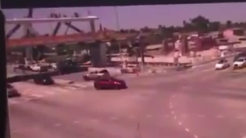
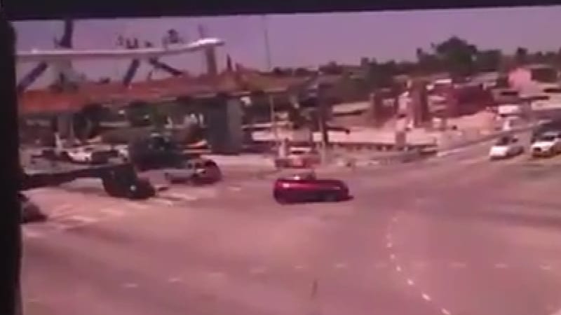
Of interest: two consecutive traffic-cam frames (phone video frames 049 and 057) show that both the canopy and deck were cracked and falling while the canopy above member 12 hasn't dropped significantly (this was also observed in frames 76-77-78 of the truck-cam video, as noted in my post of 22 Jun 19 22:31):

Frame049_wirugq.jpg

Frame057_nea6ph.jpg


The methodology I used is as follows:
[ol 1]
[li]Use VirtualDub to crop a 640x360 section of the original 720x1280 video, resize it by a factor of 400% using nearest neighbor algorithm to 2560x1440, and export a numbered image sequence. As noted in my post of 22 Jun 19 22:31, the nearest neighbor algorithm minimizes enlargement artifacts by duplicating existing pixels instead of interpolating in-between pixels.[/li]
[li]Select the 9 "best" consecutive frames of the traffic cam footage. This was difficult because the phone was not held steady, a person to the left was moving into and out of view, and the frame-rate of the monitor and phone were out of sync, causing subtle scan-line artifacts. In a few cases two traffic-cam frames were melded to create double-exposed or half-and-half spliced images, so I decided to not post a cropped video.[/li]
[li]Use IrfanView to incrementally crop the edges of the images so the final 1600x900 versions were aligned. None of the images were rotated for better alignment.[/li]
[/ol]

ADD: Here is a cropped version of the video - I'm pretty sure it used the same source.
 
MikeW7 said:
which shows that both the canopy and deck were cracked and falling before member 12 was pushed off.

I would argue this conveys imprecise understanding. It is totally expected that canopy and deck would move before you see any movement at base of 12. All it takes for deck and canopy to move as shown is for compression in 11 to no longer counterbalance tension in 10. Member 12 Node 11/12 does not need to be kicked out for this to happen. Member 11 only needs to be displaced or crushed shorter in the order of millimeters, and that is not visible on camera. A computer animation of collapse with millisecond by millisecond forces would make this point clear.
 
Status
Not open for further replies.
Back
Top