JAE
Structural
- Jun 27, 2000
- 15,555
A continuation of our discussion of this failure. Best to read the other threads first to avoid rehashing things already discussed.
Part I
thread815-436595
Part II
thread815-436699
Part III
thread815-436802
Part IV
thread815-436924
Part V
thread815-437029
Part VI
thread815-438451
Part VII
thread815-438966
Part VIII
thread815-440072
Part IX
thread815-451175
Part X
thread815-454618
Check out Eng-Tips Forum's Policies here:
faq731-376
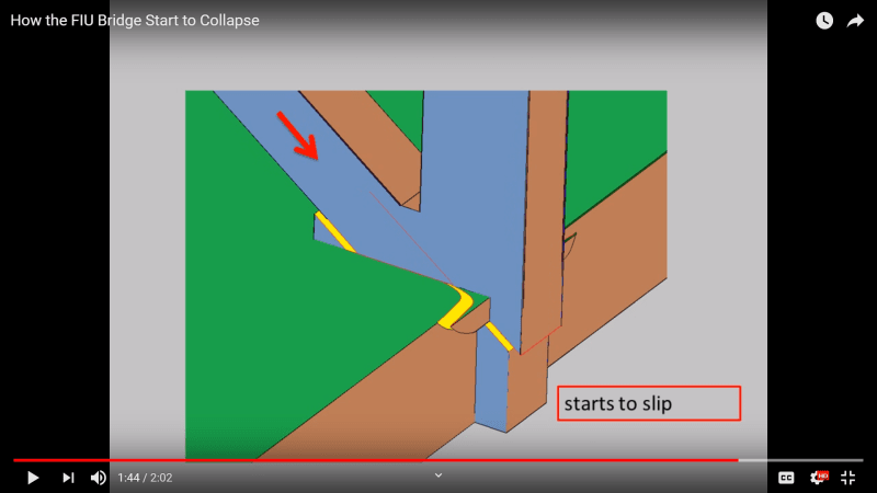
![[flame]](/data/assets/smilies/flame.gif "[flame] [flame]") I had to watch it a few times to absorb it all. Sad the view count is only 2k.
I had to watch it a few times to absorb it all. Sad the view count is only 2k.