Continue to Site

Eng-Tips is the largest engineering community on the Internet

Intelligent Work Forums for Engineering Professionals

  • Congratulations KootK on being selected by the Eng-Tips community for having the most helpful posts in the forums last week. Way to Go!

Miami Pedestrian Bridge, Part XI 32

Status
Not open for further replies.

JAE

Structural
Jun 27, 2000
15,444
A continuation of our discussion of this failure. Best to read the other threads first to avoid rehashing things already discussed.

Part I
thread815-436595

Part II
thread815-436699

Part III
thread815-436802

Part IV
thread815-436924

Part V
thread815-437029

Part VI
thread815-438451

Part VII
thread815-438966

Part VIII
thread815-440072

Part IX
thread815-451175

Part X
thread815-454618


Check out Eng-Tips Forum's Policies here:
faq731-376
 
Replies continue below

Recommended for you

MikeW7 (Electrical)28 Jun 19 17:54 said:
These are important questions that need answers
So correct. Questions that need to be answered throughout the industry and anywhere technology is used and lives are in the balance.
 
jrs_87 (Mechanical) 28 Jun 19 18:53 said:
For the record, FIGG successfully produced at least one small bridge.
Small, but simple. It's not the smallness of the bridge that's the problem, it's the complex close-packing of elements in the small volume of the 11-12 junction/diaphragm area. Did FIGG "shrink" the element spacing of a structurally sound design and not expect any problems? Was the FEA software smart enough to compensate for non-linear (or exponentially greater) effects that resulted when elements (especially the drain and conduits) were packed closer than normal?

EDIT ADD: Apologies for posting three nearly identical rants. Working in the garage on a hot muggy day....
 
MikeW7 (Electrical)28 Jun 19 19:32

Agreed. This project was such an unusual aberration, it's important for the engineering community to uncover every relevant detail. I can tell you this about this bridge> I felt offended the first time I saw it. It was so patently absurd to me right off the bat. But it was indeed built, so that means I'm the absurd one? Do you get the point I'm trying to make? Perhaps our interest in this thread is an effort to help others not fall into the same trap FIGG fell in? But then I saw this video with the school buses and I became became indignant. Thirty feet wide cracking bridge, 30 foot school bus under it. Do the math.

This cannot go unanswered.

2019-06-28_4_zfqifu.png
 
Mike W7 said:
Was the FEA software smart enough to compensate for non-linear (or exponentially greater) effects that resulted when elements (especially the drain and conduits) were packed closer than normal?

You do calculations like shear friction by hand. These types of calculations are not black and white and are difficult to program into FEA. You would have to program all the rebar through the critical shear sections. The program would have to figure out where the critical sections and pour joints are. I haven't seen any software that can do that yet. You would need a pretty good GUI to efficiently input all the rebar.

Part of the issue is that engineers get answers from software but it doesn't give you all the critical answers you need. The computer turns off the mind.
 
jrs 87 said:
Agreed. This project was such an unusual aberration, it's important for the engineering community to uncover every relevant detail. I can tell you this about this bridge> I felt offended the first time I saw it. It was so patently absurd to me right off the bat. But it was indeed built, so that means I'm the absurd one? Do you get the point I'm trying to make? Perhaps our interest in this thread is an effort to help others not fall into the same trap FIGG fell in? But then I saw this video with the school buses and I became became indignant. Thirty feet wide cracking bridge, 30 foot school bus under it. Do the math.

I have designed a lot of difficult structures. I don't see this bridge as particularly difficult. I think the hardest part to design would be the live load all on one side of the deck. The torsion is difficult to get out of this bridge. The mistake that was done was fundamental and could have been made on a more typical structure. A lot of people criticized the shape, the fact that it was concrete, the determination of the pylon height etc. I think it is good to push the limit of design and aesthetics but when you do that, you can't cut corners and you need thorough reviews. If you can't build bridges and buildings based on aesthetics, our urban landscapes would be depressing to live in. Good aesthetics are important, complying to structural codes is mandatory.
 
You can’t design a junction like that with FEA, hence the failure surface not showing up in their rainbow plots.
 
Earth314159 said:
I haven't seen any software that can do that yet.
Modern integrated circuit design software has progressed over the past 40 years to the point where desktop CPUs now contain over a billion transistors, so I'm absolutely amazed that structural design software is that primative. Any idea why?
 
The structural design software isn't primitive, but concrete isn't a homogeneous or linearly elastic material. It's non-linear and reacts differently to tension and compression, making its 'shear' behavior very complex and subject to wide variation. There are numerous different ways that are used to model reinforced concrete, and none of them are really very accurate. You really can't break concrete down into 'finite elements'; it can really only be analyzed on a macro scale.

There are just some things that even the most sophisticated computers and software still can't handle very well, like weather prediction and predicting the response of concrete to loading.
 
Mike W7 said:
Modern integrated circuit design software has progressed over the past 40 years to the point where desktop CPUs now contain over a billion transistors, so I'm absolutely amazed that structural design software is that primative. Any idea why?

A lot of people are surprised by that. Structural engineering is not as black and white as people think. The behaviour of concrete (and other materials) is complex. There have been attempts to write non-linear analysis with an-isometric materials but even with these programs the input is too complex and it takes far too long to run to be of any practical use. To properly capture the true behaviour of concrete, you need a lot of elements and they are all non-linear. I can't even imagine how that information can be inputed into a computer.

A typical design approach is to start with a concept and do some rough hand calculations. You do some 2D FEA with what you believe are the critical combinations. You then do a 3D analysis with a whole bunch of load cases and combinations. If you get the results you expect, you are likely on the right track. The analysis gives you a reasonable load path but it is not necessarily 100% correct. Minimum rebar requirements assures the load path can adjust from the theoretical load path.

It takes intelligence to figure out what is critical and how to bound you solutions. Once you do a linear analysis, you have to know what will be critical and where your assumptions will likely be conservative or un-conservative. That is why review is important in structural engineering. A structural engineer also needs methods to double check themselves. You have one kick at the can. There are no prototypes with what we do. It takes a lot more in the analysis than just working with a computer.
 
FIGG used FEA to analyze local stress/strain change vs PT bar tension. They used a difference filter to look for rainbow at the deck and did not find one. BTW, FIGG in presentation stated calculation reviews were done by independent party. Who?

The FEA model in no way has enough data to predict chaos in a cracked structure.

Not to put down engineers, but medical doctors know better how to diagnose because they deal in almost 100 percent failure conditions. We can learn from them. You have to know when to discard a test result. FEA test fail>close road/not embarrassed about it, FEA pass>close road/feel sheepish/keep checking NOT FEA pass>road open/feel confident/checking can wait 2 days
 
Thanks for the feedback. So the root problem is really unknown variables in the manufacturing process - things like aggregate distribution and rebar adherance that can't be modeled even as statistical anomolies. Very enlightening.

My rants earlier today were based on an assumption that structural design was modular, like semiconductor design: each structure "module" had well-defined internal properties, and connecting modules together was a process of insuring the boundary conditions matched. Apologies to everyone for my profound ignorance....
 
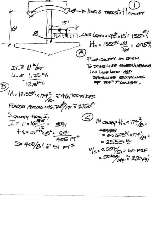
I have long been concerned about the stability of this structure under unbalanced linve loads and as a structure with flange stability requirements.
So lets try this - URGENT !! PEER REVIEW REQUESTED. Please.
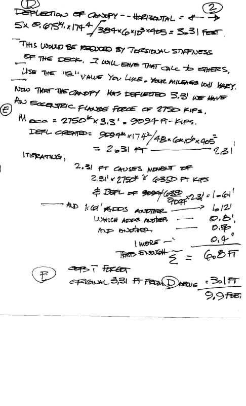
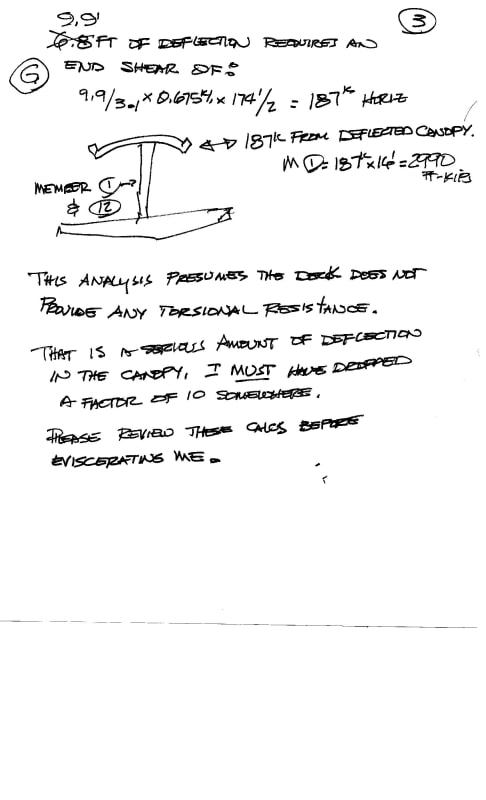
I did some calcs - unfortunately I have no skills at graphics and minimal if not negative skills at typing. So the calcs are in felt tip pen. 3 sheets, with cap letters in a circle to aid in referring to something.
And I fear I have made an error so this calc is NOT FOR CONSTRUCTION. But perhaps it will stir some curiosity in someone.
I hope the calcs are kinda self explanatory.
Now I must grit my teeth and await the criticism.

FIUCANOPYCALC0001_q0dsfy.jpg


FIUCANOPYCALC0002_y6jg2f.jpg


FIUCANOPYCALC0003_igm55o.jpg


OK - hit me with what you got. I'll get over it - maybe.
 
I am thinking I used wrong value for "E". What is proper "E" in units of feet?
KSI/inch = KSF/foot or Kx12x12/1 footx12 = 72000 ksf? So I am off by factor of 12 ? That feels better.
It has been about 15 years since doing this stuff - -
EDIT
Did a bit of unit conversion - found a reference that addressed E in different units.
Found E = 864000 Ksf which means I only overestimated the deflection of the canopy as a diaphragm by a factor of 144.
Dividing the 9.91 feet by 144 gets a deflection of 0.069 feet or 0.82 inches.
That is stiff enough to do the job.
Clearly the 9.9 feet would be a rotation in the 30 degree range and would be self un-loading.
The canopy as a beam is 174/16=span depth of 11. That looks stiff enough.
Sorry for the big number.
[highlight #73D216][/highlight]
 
Vance Wiley said:
I have long been concerned about the stability of this structure under unbalanced linve loads and as a structure with flange stability requirements.

I'll try to go over it but I have to work tomorrow. Check the out-of-plan bending in the diagonals as well which is required to distribute the warping torsion. It looks like in C that you assumed the canopy has lateral resistance at both ends.

This is a similar problem to cable stay bridges with only a central line of cable stays. In these cases, you only have St. Venant torsion in the deck (and may be some local warping torsion near the ends of the deck). I can't see second order effects on the cable stays helping too much. This is why I think getting the torsion out is one of the hardest parts of the design. You also have to think that there are significant aero-elastic concerns in the torsional mode.
 
Thank you - and yes, the only thing I see that provides a lateral support to the canopy is member 1 and 12. 12 is / will be/ would have been OK when the pylon is cast around it.
EDIT In thinking about it, member 2 and 11 will help reisst the out of plane reactions from the canopy, because they are also "fixed" at the deck and backed up with the diaphragms. End Edit.
And as I added in a subsequent post, I think my deflections are off by a factor of 12 - plus whatever I missed in choosing E=6,000,000 (inch units).
Lateral bending in webs is maybe a combo of bending and torsion because of the sloping diagonals ? Ignoring torsion and Using two 24x21 sections only and about 33 feet of trib to a node I see:
90#LLx15'x8'x33'=356 '-kips. M/S = 356'k/(2x24x21x21/6)= 1210 psi. This is to be combined with prestress remaining and/or tension in one diag and compression in the other diagonal.


Earth314159 (Structural)29 Jun 19 03:14
Earth314159 said:
...whole bunch of load cases and combinations...
Earth Irrational π, your entire post is spot-on. In fact, all the posts this week have been well worth the time to read. Thanks.

9781441917454_p0_v1_s260x420_db25wi.jpg

Introduction to Nonlinear Finite Element Analysis:
 
MikeW7 said:
Modern integrated circuit design software has progressed over the past 40 years to the point where desktop CPUs now contain over a billion transistors, so I'm absolutely amazed that structural design software is that primative. Any idea why?
That is an excellent question. And I have no ready answers apart from the results aren't readily applicable to legacy codes.

HotRod10 said:
The structural design software isn't primitive
Most of the stuff I see is. For SpaceGass which is big in a few countries is based of windows 3.1 and is still used as a primary structural tool,

HotRod10 said:
concrete isn't a homogeneous or linearly elastic material. It's non-linear and reacts differently to tension and compression, making its 'shear' behavior very complex and subject to wide variation.
All of which can be accounted for.

HotRod10 said:
There are numerous different ways that are used to model reinforced concrete, and none of them are really very accurate. You really can't break concrete down into 'finite elements'; it can really only be analyzed on a macro scale.
Finite elements make up the macro scale. Sure there is plenty of non homogeneity but that can just as easily be considered on the micro scale as it can on the macro scale. The macro is just the summation of finite element interactions.

HotRod10 said:
like weather prediction and predicting the response of concrete to loading.
Not even close. Weather is fundamentally a chaotic macro system and one that doesn't readily partition. At the micro level you have your element size is tiny, the current properties are unknown and the scale is insanely massive.\\
FEA with sensible element sizes is possible for most structural analysis particularly because you can generally partition off sections. Material properties are very well know within though there is also know variance.
 
"Weather is fundamentally a chaotic macro system and one that doesn't readily partition."

So is concrete. At least fluid compression and expansion is linear; not so with concrete. As I said non-linear and non-homogeneous makes for large variability, especially on the micro scale (and I'm talking inches, not microns).
 
Concrete is very hard to model. We can’t even model a concrete slab from first principles. We still rely on empirical methods to assess basic things like shear capacity, bar anchorage, etc.

Add reo, PT rods, complex geometry to the mix and it’s near impossible.
 
Status
Not open for further replies.

Part and Inventory Search

Sponsor