Eng-Tips is the largest engineering community on the Internet

Intelligent Work Forums for Engineering Professionals

  • Congratulations waross on being selected by the Tek-Tips community for having the most helpful posts in the forums last week. Way to Go!

Miami Pedestrian Bridge, Part XI 32

Status
Not open for further replies.

JAE

Structural
Jun 27, 2000
15,432
0
36
US
A continuation of our discussion of this failure. Best to read the other threads first to avoid rehashing things already discussed.

Part I
thread815-436595

Part II
thread815-436699

Part III
thread815-436802

Part IV
thread815-436924

Part V
thread815-437029

Part VI
thread815-438451

Part VII
thread815-438966

Part VIII
thread815-440072

Part IX
thread815-451175

Part X
thread815-454618


Check out Eng-Tips Forum's Policies here:
faq731-376
 
Replies continue below

Recommended for you

After a quick scan of the FIU information outlined by MikeW7 I found some flaws in the Mar 15, 2018 Presentation

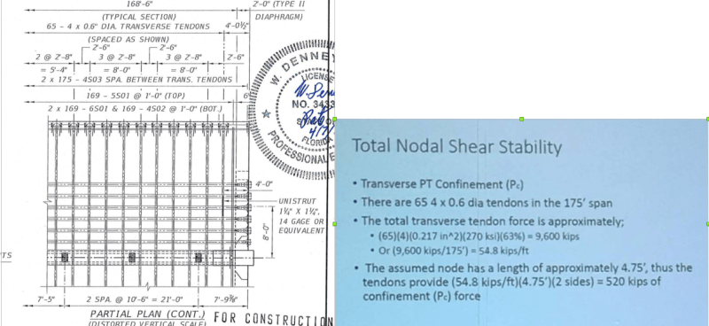
(1) Confining force by averaging the lateral tendons not justified.

Screenshot_from_2019-06-28_03-26-14_ypprfk.png


The 11/12 area did not have any transverse tendons at all and the next nearest one was 4.04’ away from the Diaphragm II or 4.915’ from the Member 12. In the presentation 11/12 was assumed 4.75’ long to have transverse confinement based on a total force from 65 tendons divided by the 175’ length.

(2) Altered failure mode by the shifted construction joint (CJ) not appreciated and reductions in strength caused by the presence of the five cast-in sleeves and pipe were omitted in the presentation.

Screenshot_from_2019-06-28_00-31-23_exbjid.png


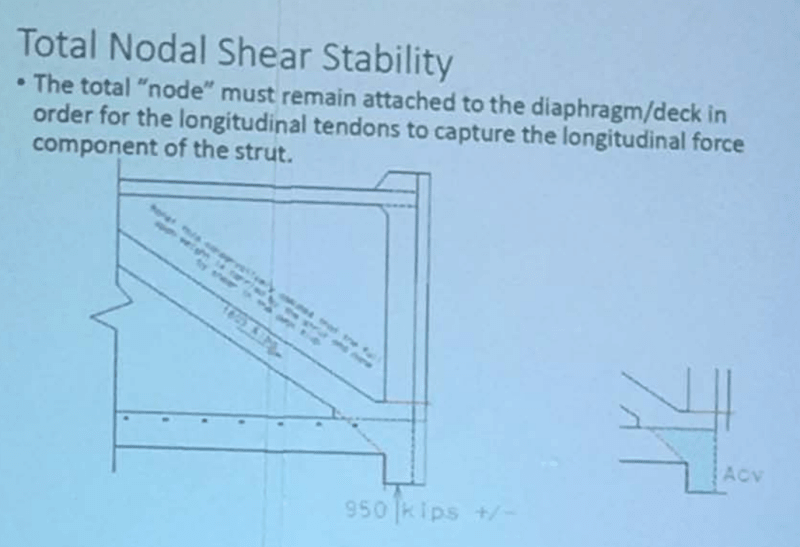
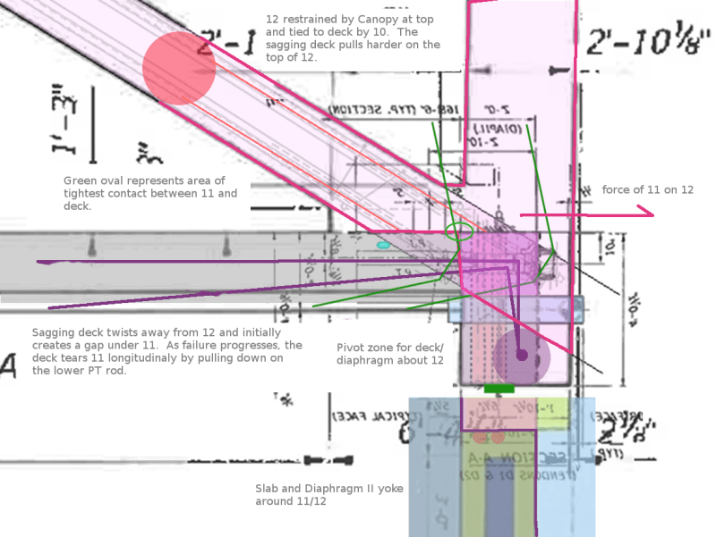
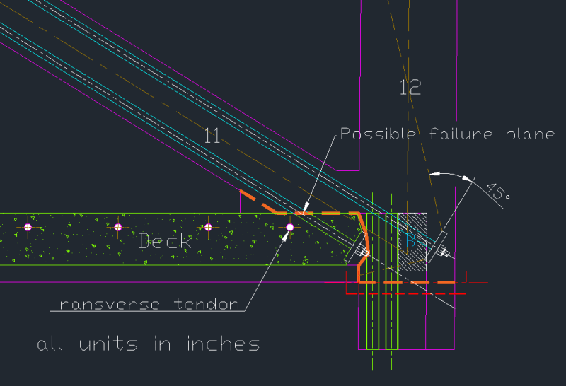
In the presentation it was assumed the rebar crossing in area the Member 12 bonding with the deck (including Diaphragm II) would participate in resisting shear. This area shown in the presentation is a triangular area (from the deck) plus a full cross section of 2’ wide by 4’ deep from Diaphragm II.

Screenshot_from_2019-06-26_15-51-26_lyxwyf.png


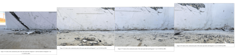
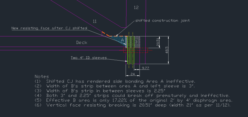
In the field the construction joint had shifted. Therefore 11/12 shear capacity based on the above assumption is no longer justified and the reason is explained in a sketch I prepared below (unit in inches).

Shifted_CJ_xunejz.png


It is obvious once the CJ had shifted the bonding area A on the two sides of 11/12 would cease to resist shear against 11/12 but stayed as integral parts of the deck. The resistance then would be transferred to the vertical face between the deck (Area A) and Member 12 (Area B).

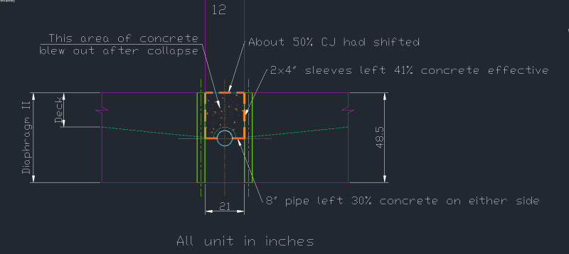
The presentation had assumed the full cross section of Diaphragm II, on both sides of Member 12, would be available to resist shear. However by placing two vertical 4” ID sleeves on each side and one horizontal 8” ID pipe this bonding surface B was compromised leaving a mere 17.22% area effective.

The designer in the presentation did ignore the concrete contribution to resist shear and relied heavily on the rebar crossing the bonding areas he had assumed. In the field the 11/12 slid along the CJ, pulled out the vertical face between Area A and B and managed to shear out of position along the 8” horizontal pipe. This is because along the 8” pipe the concrete area is at its minmum while at the same time the rebar are embedded with the least amount of concrete due to the sheer volume taken up by the 8” pipe. The lack of concrete surrounding the rebar, at the failure plane, has eventually led to many steel bars seemingly clean and undamaged without any concrete fragment attached after the collapse.

In summary the failure mode brought about by the shifted CJ was not appreciated. The significant capacity reductions in the 11/12/deck joint, caused by embedding four vertical 4” sleeves and one horizontal 8” pipe at the critical positions, were not considered. These shortcomings led to the bridge failed materially different to the Mar 15,2018 presentation. Therefore the assurance of the bridge was safe on Mar 15, 2018 was based on some serious flaws.

It would be fair to say the designer did not have the time to go over the cracks photos as we did and so his presentation could not have the refinements I have introduced. However the presentation was crucial to persuade every attendee to the Mar 15, 2018 meeting that the bridge was safe. Therefore any flaw that concealed the true condition and led to an inaccurate assessment of the bridge safety should have been responsibly avoided.
 
earth said:
The shear plane in the presentation was not the critical shear plane. That was the main issue.

Yes. The calculation presentation focussed on non-critical aspects of the design e.g. deck flexural strength and non critical shear planes. The calculations ignored the criticial failure surface. FIGG was presumably aware of the crictical failure surface as they were devising a method to "capture the node". So it would appear the calculation presentation was somewhat of a ruse designed to placate the others, to give FIGG a bit of breathing room to devise the fix.
 
Tomfh (Structural) said:
So it would appear the calculation presentation was somewhat of a ruse designed to placate the others
Lets not forget the Power Point Presentation had to have been prepared before March 15, and that was the only thing the EOR had available at the meeting. So I have to think he was presenting something he did not totally support. That does not excuse him for all the "no safety concerns" after he had seen the cracking just before the meeting. Those statements are not unlike those a coach at a Junior College might say to his team before a football game with Clemson or Alabama.
All in all, he is left in a world of hurt. It has been a particularly tough time for him - a bridge in the street and his phone went thru the washer. What's next?
 
Or better, the deck starts to sag, taking the lower PT bar with it while the upper PT bar is still embedded in 12. This splits 11 while also creating the twisting in the slab around 12.
 
Vance said:
Lets not forget the Power Point Presentation had to have been prepared before March 15

Sure, but the presentation included photos of the big cracks. So they can't claim they had no idea it was cracking like that when they put together that presentation.
 
The four photos you have presented of the member 11 and 12 to deck area - show serious horizontal splitting of the east face of that zone, particularly the fillet between 11 and 12 - am I right?
It looks like each of the photos laps the adjacent pic by about 50% but the takeaway is the same. Serious cracking about 8" above the deck surface. That is about where the top of the 7S01 shear friction bars was. Such a lack of confinement reinforcing.
In your sketch of the blow out area - it seems the departing block was defined by the PT confinement of the anchorages of D-1 at the upper region and expanded diagonally below that zone. Much of what I see in the end of that deck section/diaphragm below that PT anchorage (from OSHA pics) looks like diagonal tension.
The pipe sleeves probably defined two zones - one south of and one north of the sleeves, with a weakened zone at the sleeves. That likely allowed each side - A and B - to fail separately, IMO. If that is a valid idea then there were 3 zones of failure, each with different modes and stiffnesses. +


saikee119 (Structural)28 Jun 19 02:41

Good post and drawing.

On page 111 of OSHA report, this quote appears:

OSHA Report said:
There was a 4” and 4½” diameter plastic pipe placed right against the columns in diaphragm II.

Elsewhere in report 4" only is shown.
 
Saikee119 has shown the failure zone definitively. Consider that block A remains intact after the collapse and block B is scooped out.

I propose that the deck and diaphragm form a yoke around 11/12 (under 11 and around 12) and are attached at the base of the diaphragm, otherwise detached and free to pivot about the attachment (rebar can only offer limited resistance and acts as a damper to movement). The detachment of Saikee's Block B from the diaphragm allows the structure to sag. It is the sagging structure that twists the diaphragm/slab off of 12 and also opens the crack beneath the heel of 11. Note the point of tight contact between 11 and the deck highlighted below with the green oval.

The sagging structure is actually pulling the lower 11 PT bar down and tears 11 longitudinally. This tearing is what was initially visible as the fine longitudinal cracks from the time when the form work was removed. The upper 11 PT bar is not free to move down. The tension cracks at the upper fillet between 11 and 12 is further proof of 11 being pulled apart by the two PT bars anchored in the conflicted members (yellow oval).

This complex cause and effect would not likely have been apparent to the workers, nor was it apparent to the Engineers though all the signs were visible from the outset.

Deck_11_Overlays.2..6_ffptxf.png


Failing_Bridge_Green_Circle_nzhihx.jpg


11_12_fail_yellow_circle_lhzxfy.png
 

Sym P. le (Mechanical),

Block B could come out as a wedge had the CJ cracked through. I am not suggesting this had happened and the cracks photos do not support it either. I am preparing another sketch to show the possible failure plane. An accurate knowledge of the actual failure plane is essential to understand why putting the tension back in Member 11 killed the bridge.

Vance Wiley (Structural),

The four photos of the CJ cracks are intended to demonstrate movement covers a distance up to but not including the vertical sleeves. After the sleeves the separation changed direction and I am about to show it with a sketch. I only lined up the four photos but couldn't overlapped them as their magnifications may be different to each other.

The triangular fillet can be seen without the bottom crack so it was still part of the deck. How much 11/12 moved away from the deck can be estimated by the horizontal width of the fillet's diagonal crack. I would say the movement could be easily 5 to 10mm. This magnitude corroborates with the separation between concrete and sleeve at the west side. The fillet crack shows conclusively 11/12 has separated from the deck at the front or the south side.

I believe there should be only two zones of failure. Every part on the deck should be substantially rigid but minor cracks and separation of inconsequential nature could be present. The failure zones with 11/12 can be seen to have lot more serious within-zone cracks and separations.
 
In an earlier post (12 Jun 19 01:31) I mentioned that FIGG's main business was designing immense structures, and alluded to the fact that American automakers took years to figure out how to properly design smaller automobiles. One of Detroit's first downsizing "tricks" was to start with a familiar design and remove short sections of length and height from a large clay model and blend the edges together (this was an era when CAD meant Clay Assisted Design). Is it possible FIGG used a similar approach (to save money) and "downsized" what they were familar with by simply grouping CAD building blocks (drains, etc.) closer together, and this close packing caused a superposition of stresses and weaknesses that were much higher (exponential instead of linear) than what they expected? Is it possible their FEA software failed for the same reason - it wasn't designed to model closely-packed voids?

Back in college I wrote a finite-element simulation for magnetic fields in solids, and I remember that managing the boundary conditions at a solid-air interface was a nightmare. I assume the same holds true for solid-air interfaces in structures.

I'm not trying to absolve FIGG from blame, I'm just trying to understand why they were so adamant about their simulation results.
 
saikee119 said:
... to understand why putting the tension back in Member 11 killed the bridge.

Re-engaging the PT bars in 11 was a reckless move based on elementary principles. The structure needed to be shored up while decisions were made to rehabilitate the structure or remove it. Understanding this failure sequence/mechanism adds to the library of information for future reference and would have been useful for rehab purposes.
 
A prediction of the failure plane based on OSHA report photos

Using the photos from OSHA report I venture to suggest a possible failure below.

Capture2_1_qyegao.png

Section of 11/12/deck joint with PT rods, transverse tendons and cast-in items added (edited)

The firs part of the above failure plane is the shifted CJ. OSHA Fig 18 shows cracks appeared as soon as the bridge was first required to support its own weight by removing the shoring while the bridge was still at the roadside casting yard on Feb 28, 2018. Subsequent OSHA Fig 32 to 38 show the CJ had shifted about 5 to 10mm after its tension was removed and the bridge was resting at its final position on Mar 10, 2018. OSHA Fig 63 to 70 indicate the lower PT rod firmly anchorded to the deck.

I have assumed 45 degree stress distribution from the anchors and the lines of influence are depicted by brown dotted lines.

After passing through the lower PT rod anchor the last part of the failure plane is less certain because the initial failure plane may have been complicated by the consequential damages caused by the final separation of 11/12 from the deck.

An importance feature of the above sketch is that the lower rod was clearly holding up the deck while the upper rod was more effective on 11/12. The alternate stressing and de-stressing of the two rods would encourage movements and exacerbate the distressed joint. This is because the lower rod was compressing concrete stiffer than the upper rod. By releasing or applying same tension, typically 50 psi per rod at a time, the strain would be different in the two rods. Different strains cause concrete to deflect by different amount and the difference widens and elongates the cracks. Personally I consider the two rods in Member 11 badly arranged at a position seriously compromised by the embedded items. The upper rod especially became more flexible because as it had more self-arranged weaknesses than the lower rod. Subsequently a simple tensioning or de-tensioning of the two rods could generate uneven strains leading to detrimental damages to the bridge. The uneven strains from the same tension force of the two rods could be the very culprit responsible for the bridge collapse.

Capture3_1_n8jr2l.png

Rear view of Member 12 with Diaphragm

It is certain that bonding surface of the diaphragm to Member 12 would be compromised by the 4” vertical sleeves leaving just 41% concrete effective in the vertical direction.

Additionally due to the presence of the 8” pipe cast horizontally the concrete at the centre line of this pipe was necked to have just 30% concrete on either side.

Bounded by the above weaknesses of a shifted CJ at the top, vertical sleeves on both sides and a horizontal pipe at the bottom the enclosed concrete suffered a blow out during the collapse.

Before the collapse 11/12 was retained in position by the rebar many of which could act as dowels. The ferocity of the cracks would suggest some yielding in the steel and internal local concrete crushing, especially surrounding the rebar.
 
saikee119 (Structural)28 Jun 19 10:33 said:
I believe there should be only two zones of failure.
Your "yoke" reference is quite good to describe the more direct shear zones which you have designated "A"
I suggested 3 zones can be defined, as follows:
1) cold joint at top of deck - extends to north of the lower PT, Mu = 0.6
2) zone "A" - integrally cast zone of primarily "shear friction" defined on each side by the PT anchorages of D-1
3) blow out zone "B" of primarily diagonal tension.
A different method of calculating resistance/capacity is appropriate for each zone. Whether the resistances are additive or not is another issue. If they fail simultaneously then it may be appropriate to combine them. But it appears that the "cold joint" failed first and somewhat independently of zones A and B. But we can't see what was happening at zones A and B until the cracking at the deck surface beside 11/12 became visible and the cracking in the north face of diaphragm 2 also became visible.
As to A vs B, I totally agree that the pipe sleeves created two zones, with a soft zone between from the sleeves.
Whether A and B did or did not fail simultaneously may be of little import, because it all ended up in rubble over a time span of about two blinks, maximum.
 
MikeW7 (Electrical)28 Jun 19 15:09 said:
I'm just trying to understand why they were so adamant about their simulation results.
We think airplanes can fly themselves so we crash. We think they can land themselves so they crash. We think trains can run themselves so we text our girlfriend and we crash. We forget phone numbers because we use speed dial - "you are #3" - and if I wash my phone I don't know how to call you.
We think a computer can tell us everything so we do not need to pay attention. We are overwhelmed by the volume of printout produced so none of the numbers are significant. We do not touch the problem with any depth of understanding or delve into it because we trust the computer to do it for us.
Why the hell are we even necessary? We are abdicating our position of authority at the top of the intelligence pyramid and apparently willing to fade into oblivion like the neanderthals did.
I understand the feeling - if the computer has already solved it, my hand check is like watching a football game after it has been played - the score is in, so its over.
We can get engineering answers without even understanding elementary engineering principles.
I spent a long time translating Ed Wilson's structural program from Fortran to interpretative Basic because we were a small firm and cold not afford an IBM 1130 (quarter million in 1980 dollars). This was 1980 period - just before the PC was introduced so I was using a CP/M computer with 64K memory and an 8" 600K floppy.
So I thought about selling copies and advertised in ENR. Then I began to think I could be an accessory to a collapse. This program would allow untrained people to find and "present" a complicated analysis of an indeterminate structure when they had no idea what was going on. No copies were sold.

 
Vance Wiley - My point was that FIGG were experts at building large structures, and were very confident in their simulation expertise, but were obviously surprised at the discrepancy between what they predicted and what actually happened, as in "this has never happened before".

My question is "Was this because their hand calculations and simulation methods/models were inappropriate for this small-scale task with tricky geometry, but they didn't know it?" Were there non-linear complications present that they literally had no way of predicting, either by simulation or hand-checking. Were there hidden, "day one" problems in the software that hadn't been exposed before, but appeared because of the unique nature of 11-12 junction. These are important questions that need answers to prevent the next "never happened before" disaster. Hopefully the NTSB report will address this.
 
Status
Not open for further replies.
Back
Top