Continue to Site

Eng-Tips is the largest engineering community on the Internet

Intelligent Work Forums for Engineering Professionals

  • Congratulations KootK on being selected by the Eng-Tips community for having the most helpful posts in the forums last week. Way to Go!

Miami Pedestrian Bridge, Part XI 32

Status
Not open for further replies.

JAE

Structural
Jun 27, 2000
15,444
A continuation of our discussion of this failure. Best to read the other threads first to avoid rehashing things already discussed.

Part I
thread815-436595

Part II
thread815-436699

Part III
thread815-436802

Part IV
thread815-436924

Part V
thread815-437029

Part VI
thread815-438451

Part VII
thread815-438966

Part VIII
thread815-440072

Part IX
thread815-451175

Part X
thread815-454618


Check out Eng-Tips Forum's Policies here:
faq731-376
 
Replies continue below

Recommended for you

The neighboring compression in the concrete may be different near each rod, but the extension of each rod should be the same for the same applied tension. Since the amount of concrete the rods pass through is majority in the diagonal even the differences in the deck area are small contributors; possibly a few percent.
 
One thing I've been wondering: Why did both ends of the bridge not crack similarly? And can anything be learned from the fact that they didn't?

Up to a point, it seems they did. On Feb. 6, 2018, Bolton Perez & Associates performed a visual inspection of cracks on diagonals 3 and 10 after PT bars tendons No 2 and No 11 were stressed. They stated, "We believe, this first stressing operation has temporarily created tension on members No 3 & No 10; thus, creating cross sectional cracks transferring the tension loads to the steel on these members." (p. 1, FIU Pedestrian Bridge / BT-904 Crack Inspection Report). The OSHA report then indicates that on Feb. 26, after hearing a loud popping sound when the shoring under the span was removed and it was self-supporting, "The employee from the TSG and one of the employees from the MCM walked over the bridge and noticed cracks at the bases of diagonal 2 and 11." (p. 24).

Thus, up to a point, the span ends seemed to be responding similarly to stresses. However, after the move and then the de-tensioning of 2 and 11, that clearly wasn't the case, with only the north end developing progressively larger and, frankly, scary cracks. Is it clear why? Was it because diagonal 2 was much beefier than diagonal 11, with different geometry and maybe more rebar? Or because the deck ends were different, with the north end less reinforced? Or because the north end was moved much farther, over a bumpy median and was also cantilevered farther from the supports? Or because the south end of the span was designed as the actual end of a bridge, and the north "end" was intended to be a temporary intermediate construction phase? Or some combination? Or something else?

I apologize if the comparison of the two end responses has been addressed earlier, or if the question is just plain dumb. I'm not an engineer but I worked with engineers and obtained environmental clearance for many federally funded bridges, so they got used to me asking dumb questions!
 
Wetlander (Specifier/Regulator)30 Jun 19 02:55
Your post seems well reasoned to me.
 
@saikee119 - Thanks for your response. Modelling unconventional use of rebar might be unconventional or just darn near impossible. I've been thinking out loud and trying to incorporate what I see or don't see into a better understanding of the collapse. My model may not be perfect but it is a work in progress and I welcome anyone to critique what I put out. I'm learning a lot from these threads.

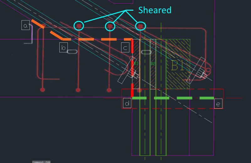
I accept your analysis of the shear planes wholeheartedly because it moves past a lot of what obviously wasn't happening, shear planes that weren't working as such. This allows for more freedom to consider why the bridge would creep for almost a week (if not from the very time the scaffolding was removed) without collapsing. As I looked closer, I noticed that even your concept of plane B, which is perfectly sensible, may have been an illusion. That is not to dismiss your work, but to further embrace it. If it turns out that the design of the north end of the bridge is just an illusion, so be it if that is where the evidence leads. Key design elements are absent and those that are present are pressed into unconventional service ... for a time. I'm hard pressed to accept simple answers, especially in complex circumstances. OSHA's explanation, though it maybe perfectly valid, does not seem fully developed and that opens the door for speculation or preferably a fuller analysis of the matter.

My earlier analysis with a torque element and the door closer was an idea for an explanation of the slow motion train wreck. If all of the conventional door stops are removed, it seems to me that what we are left with is one or two feet of the diaphragm and 12 fully and coherently bonded, with the rest of the structural elements free (cough) to move and straining under loads they were never meant to carry. I did not suggest an ultimate failure mode because once a run away condition is described, the final collapse is a moot point. I could be wrong.

One thing I forgot is that when the north end of the slab slipped off of the pylon, it seems to have sheared the two hold down rods. That would knock a bunch of concrete off of the bottom of the diaphragm.

Anyway, thanks again and I look forward to all of the posts.
 
Wetlander (Specifier/Regulator),

The point why the north end crack and not the south end has been raised before in this forum.

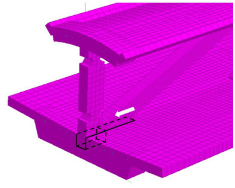
The answer was south end has a stronger joint. Although its vertical column is only 5% larger but the 3' diagonal is 50% larger casting with the same deck. There are more rebar and some of them could be placed in more strategic locations than the north end. The diagonal load on the south end is higher though.

Screenshot_from_2019-06-30_10-41-26_tszhny.png
 

jrs_87 (Mechanical),


Thanks for the link. The link has this diagram.
Screenshot_from_2019-06-30_11-16-58_d7mmws.png


which is what I have predicted and shown in the CAD figures. The above 3D diagram is on the south and not the north end.

I think people slowly realize the deck was pulling away with the force equal to the horizontal component of the diagonal member axial compression and the connection surface wasn't generous. especially at the north end.
 
saikee119 (Structural)30 Jun 19 10:25

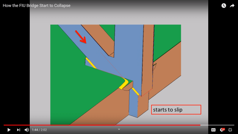
Saikee, I'm glad for that image too. Link below is for an old animation that is good in another way. Now, what we need is a true-to-life translucent solid model that can be rotated, sectioned, and animated. Ability to highlight separation interface would be a plus.

Hopefully, precisely how the PT bar tension reversals affected the area will soon be satisfactorily explained.

2019-06-30_1_prdain.png


Source: 1:44 mark (please read screamdoctor comment below video)

I don't think the entire node slid together as shown. North face of 12 and diaphragm cracked and flexed at first while holding 11 back. The discrepancy of displacement accounted for by internal crushing and rotation.
 
jrs_87 said:
High quality blog post about OSHA report from a U.K. bridge designer:

Thanks for the post!

A comment from that blog post has a great short summary of another construction collapse in the Netherlands. The engineering failings are woeful and damn obvious, but the summary of the problems inherant in the industry are equally applicable. (And also quite applicable to the recent Australian construction issues.)

 
Thanks, jrs_87 and saikee119 for the responses. It is terribly unfortunate that the FIGG analysis resulted in designing a larger diagonal 2 compared to others, but not a larger diagonal 11.
 
jrs_87 said:
That video was a scorching rebuke. I had to watch it a few times to absorb it all. Sad the view count is only 2k.
Yes. It doesn't hold back. And what is true there is certainly true in the Australian construction industry and likely also the US and across the globe. The problems go well beyond engineering mistakes.

Further reading on the collapse is also enlightening. What the video also didn't fully elaborate was that the construction joint played a huge role in that incident too. The thin prefab slabs were never roughened. There are some great picture of core sames show pretty much zero cohesion in the slab layer.

A brief english version (paywalled)
A comprehensive dutch version (pictures still tell some of the story)

Anyway much further on that needs its own topic! But it certainly is an interesting failure and extraordinarily lucky nobody was killed.
 
human909 (Structural)30 Jun 19 12:33 said:
... a great short summary of another construction collapse in the Netherlands ...

Transcript obtained from the video closed-caption subtitles, downloaded with followed by format editing to insert spaces, break paragraphs, etc.

In recent years several accidents have occurred in which buildings have partially collapsed. Four of these incidents have been investigated by the Dutch Safety Board. The Board's most recent investigation examined the partial collapse of a multi-storey car park, located next to the Eindhoven Airport terminal.

The building had a modern design with open floor plans. It’s floors were kept light and slim by using bubble deck slab floors. A bubble deck floor is constructed from individual prefabricated slabs made of a concrete base, reinforcing steel, lattice beams and plastic spheres. Concrete is then poured onto the floor slabs. The plastic spheres mean that less concrete is required, reducing the total weight.

In a conventional application the Bubble deck floor slabs span the distance between the columns in the longitudinal direction. Deflection of the slabs is the largest in the middle of the floor. The reinforcement bars ensure that the floor does not break. In the case of the Eindhoven car park the decision was made to rotate the floor slabs 90 degrees. The floor supplier and the contractor considered this solution the best to meet the design requirements for a thin floor with a long span and gradient for rainwater drainage.

EDIT: In the video demonstration, the slabs were 10mx3m. To create a 12m span, 4 slabs were turned sideways.

Rotation of the floor slabs resulted in a vulnerable floor design, as it placed seams at the locations where the deflection of the floor is the largest. No additional measures were taken to overcome this vulnerability. Owing to the coupling reinforcement bars being too short, the floor was unable to properly bear its own weight. The warm temperatures of 27 May brought about an additional temperature stress, causing the floor to collapse.

Despite deviating from the usual construction method, no attention was given to the possible consequences of this design choice. Signals were not met with a response. None of the parties saw any reason to have reservations about structural safety, although this could and should have been the case.


A shared concern for safety is not self-evident in the construction sector. The Board sees a sector characterised by a limited ability to learn and a low degree of self-reflection. Previous incidents and investigations have not resulted in improvements, while parties are all too ready to blame someone else.

Construction projects often have a complex organisation, in which multiple parties are involved at different times. As individual parties do not oversee the bigger picture, the chance of error increases. This fragmentation of the construction process also leads to a lack of clarity regarding the allocation of responsibilities. As a result, safety risks go unnoticed and no control measures are being taken.

The lack of one central party to monitor the overall construction process, and to keep other parties on their toes, is one of the most important explanations for the inadequate monitoring of safety risks. This conclusion was previously drawn by the Dutch Safety Board and it was indeed the case in Eindhoven as well.

In addition, the Board notes that the competition in the building sector is above all based on price instead of quality. If clients were to take safety more seriously, the level of safety would be increased considerably. As municipalities conduct less supervision, the final check of building constructions is increasingly skipped in a sector that takes insufficient responsibility for safety. The Board considers it high time that the building sector takes up this responsibility and implements the necessary improvements.

Improved risk management is needed throughout the building sector. Both clients and contractors must bear their share of this responsibility. To this end, the Board makes recommendations in the following areas:
[ul]
[li]Expand the existing Construction Safety Governance Code and make it less voluntary.[/li]
[li]Ensure clarity in the division of responsibilities and their coordination.[/li]
[li]Appoint a single party to take overall responsibility for risk management throughout the construction process.[/li]
[li]Investigate how this can be made mandatory.[/li]
[li]The Board expects the construction sector to apply the principles of mechanics and the associated diagrams thoroughly.[/li]
[li]Builders are expected to adopt a professional attitude by addressing any doubts and critically reflecting on their own actions.[/li]
[/ul]
 
That is quite an interesting collapse. Should that be I’m its own thread?
 
The Dutch are very blunt in their discourse, so I'd expect that to show up prominently in their investigations. One needs to know more about how Architecture/Engineering & Construction are treated in both the Public & Private sector to know what might need to change. The way the BubbleDeck was rotated was crazy. Apparently two other contractors turned down bidding on the project because they didn't like the spacing of the floor design. This suggests the engineering to meet the design was part & parcel, the contractor's responsibility.

When it comes to FDOT oversight of the FIU bridge, one has to acknowledge that the LAP (Local Agency Program) isn't unique to Florida and starts with the FHWA. Universities already operate as Quasi-municipalities, so the bureaucracy of qualification probably wasn't a major hurtle. Especially if they had T.Y Linn (FIU Planning Consultant) holding their hand. Universities are nothing, if not Federal Grant & boilerplate savvy.

FDOT's, Mr. Alfredo Reyna, PE. was working on contract from Keith and Schnars, Consulting Engineers. Keith and Schnars, looks to be mostly "Consulting". As a hired gun LAP Coordinator, his job is to merge FDOT requirements with FHWA requirements and make sure that the parties involved are adhering to the LAP & TIGER program protocols. He was very conscientious about wanting to be copied/included in all FDOT communications. As far as can be ascertained, he only saw the few crack photos from the FIGG presentations and may not have fully understood the condition of the bridge. His FDOT role, or his firm may even preclude him from making any engineering judgements.

Bottom of Pg. 84 of the OSHA Report: As a result of the blow-out, three #7 shear reinforcements at the construction joint of diagonal 11 and the deck were sheared but the southernmost shear reinforcement remained intact.
It would have been nice to see a photo showing the full CJ contact surface, after the large debris had been removed. The southern most rebar was supposedly in the crack "separated" chamfer in the 11/12 node.

Shear_Failure1_oeadit.jpg


Something to be considered, the inspectors for Bolton Perez and Associates, Inc., were hired for their knowledge and experience in oversight of the new work. When cracking became a concern, someone experienced in making assessments of cracking in concrete should have been sent out to access the work, even if it meant contacting a third party. If your firm doesn't do remedial work, then they need to recognize when they are out of their depth and get a qualified opinion.

In construction, sooner or later you deal with people who are very adapt at shortcuts, end-runs and playing two ends against the middle. It gives them an advantage over their more scrupled or less experienced competition. If any party was experienced at divining the shortest path through the entanglements of the FDOT, it was FIGG and they look to have exercised their skill in this sphere to maximum advantage; when it came to the requirements of PEER Review.
 
> human909 (Structural) 29 Jun 19 12:15

>> Quote (MikeW7)
>> Modern integrated circuit design software has progressed over the past 40 years to the point where desktop CPUs now contain over a billion transistors, so I'm absolutely amazed that structural design software is that primative. Any idea why?

>That is an excellent question. And I have no ready answers apart from the results aren't readily applicable to legacy codes.

(Long) retired integrated circuit development/test engineer here. I'm afraid the answer is that the IC design software has an easier job. Most of it has to do with the modular nature of microprocessors. The basic elements (transistors, resistors) have gotten smaller, but the inherent technology of those devices date back to the 1950s and '60s. Elements in a processor (adders, registers) frequently get reused. Note that some errors in the late Intel processors actually dated back to the Pentium I. It seemed to work, so it got reused.

The other part of it, is the development tools have been working on essentially the same problems as the overall technology improves. How do you get signals around, keep power dissipation, and make it smaller. These questions really don't change; just the controlling parameters.

FWIW, when I retired in 2001, IC layout people usually had an AA degree, though the designers ranged from BS to PhD--usually BS and MS. That layout software was intended for use by that level. It also doesn't hurt that IC designs are essentially 2D, though it's layered, with various connections at different levels.

I've been following this discussion since shortly after the bridge collapsed. Impressive work, gentlemen!


I would have like the investigator to study carefully the first set of photos to arrive at the probable cause. He/she then returns the next day to concentrate on the selected sections/portions, clear debris to get to the bottom. He should return as many times as needed to capture all the important information before the site is cleared.

I am amazed at no photo available to show the east side of the diagonal 11 after the collapse. It had a massive longitudinal crack.

Sheared off rebar was described by OSHA but without photos showing what happened after the debris and dust were cleared to show the naked steel. Shots should be taken to cover the full extent of the CJ.

The true cause of the collapse would be self evident if there are sufficient photos showing each remaining rebar to allow its bar mark to be identified accurately.

It is quite possible OSHA has access to a lot more photos and published only few good ones with the report. In the digital era I myself often take 10 times more photos than needed for a report.
 
saikee said:
It is quite possible OSHA has access to a lot more photos and published only few good ones with the report. In the digital era I myself often take 10 times more photos than needed for a report.

I find that no matter how many photos I take I can still fail to take the photo I really need.
 
I have seen video of the NTSB taking photos as the remains of the bridge were disassembled (jackhammered). There should be a dossier on the web at the time of the NTSB hearings.

SF Charlie
Eng-Tips.com Forum Policies
 
Source:
Tony Pipitone NBC 6 News Article said:
The next morning, March 13, FIGG's president, Linda Figg got involved, emailing her engineer of record on the project, Denny Pate: "Wouldn't it have made sense for us to address all of these things while we were on site? … I think it is important for you to stop whatever you are doing and address this so we can put all of these items to rest quickly."

Source:
Tony Pipitone NBC 6 News Article said:
“Don’t you worry,” replied fellow engineer Eddy Leon, adding Pate was going to travel from Tallahassee to Miami for a meeting “just to calm everybody down.”
...
Pate had already left the worksite and was heading back to FIGG headquarters in Tallahassee a half hour before disaster struck when he texted his boss, firm owner Linda Figg: “Meeting went pretty well. FDOT and FIU were represented. Our attendance and information were appreciated. We will be working on some additional ideas to better the current situations. I’ll get you more details when I get back to the office.”
 
Status
Not open for further replies.

Part and Inventory Search

Sponsor