Continue to Site

Eng-Tips is the largest engineering community on the Internet

Intelligent Work Forums for Engineering Professionals

  • Congratulations KootK on being selected by the Eng-Tips community for having the most helpful posts in the forums last week. Way to Go!

Miami Pedestrian Bridge, Part XI 32

Status
Not open for further replies.

JAE

Structural
Jun 27, 2000
15,444
A continuation of our discussion of this failure. Best to read the other threads first to avoid rehashing things already discussed.

Part I
thread815-436595

Part II
thread815-436699

Part III
thread815-436802

Part IV
thread815-436924

Part V
thread815-437029

Part VI
thread815-438451

Part VII
thread815-438966

Part VIII
thread815-440072

Part IX
thread815-451175

Part X
thread815-454618


Check out Eng-Tips Forum's Policies here:
faq731-376
 
Replies continue below

Recommended for you

MikeW7 (Electrical) said:
The most interesting frame is 057, which shows that both the canopy and deck were cracked and falling before member 12 was pushed off.

The use of the word "before" in the above may be hazardous if this can be proved incorrect later.

People with structural engineering background are more easily convinced by the following:

(a) It is more difficult to have either the canopy at the joint canopy/10/11 and deck at the joint deck/9/10 to fail prior to the deck/11/12. Each diagonal member of every truss, like 9, 10 or 11, had an axial force internally which in statics could be replaced/substituted by one horizontal component and a vertical component in a ratio according to the triangle it makes with the horizontal. Thus the force in the upper section of 11 had a reaction opponent provided by the upper section of 10 to achieve equilibrium. Similarly the bottom of 10 and 9 could hold each other in equilibrium. The joint at deck/11/12 had nothing horizontally to act against with and logically became the easiest one to fail first among the three.

(b) The canopy section on top of Member 11 is structurally redundant. By that I mean it can be removed without affecting the behaviour of the structure. Indeed a standard Warren truss does not have it.

warren_truss_ogqpzx.png


However the extra canopy section here provided the weather cover and served as anchorages for the longitudinal tendons in the canopy. The lack of structural importance of this section of canopy with Member 12 will become obvious if one examines the equilibrium condition at the joint where both meet but find neither of these two members has an opposite number to balance internal axial force with.
Since both canopy and Member 12 were rigidly joined together their member forces would have a full compliment of axial force, shear and bending moment but the axial force magnitude will be small by comparison. For example the canopy's shear, due to its half of last bay's dead weight, will be balanced by the axial force in Member 12.

(c) Had canopy/10/11 or deck/9/10 failed first then there is a good likelihood the north end could fail in a manner similar if not identical to its south end. The equivalent joint to deck/11/12 at the south end is deck/1/2. It was almost undamaged sitting on top of the pier after the collapse.

SOuth_end_not_damaged_yxqgjn.png


(d) There is an absence of photographic records and historical evidence pointing to the deficiency of either canopy/10/11 or deck/9/10. The shortcoming of deck/11/12 however was known as soon as the shoring was removed while the bridge was still at the roadside.

(e) Among the three joints of Deck/9/10, canopy/10/11 and deck/11/12 the joint deflection of the last is most devastating. Prior to the collapse 11/12 had horizontal deflection about 5 to 10mm or 1/4". Whenever Member 11 flattens its angle, by the addition of horizontal deflection to the horizontal dimension, its horizontal pushing force is increased at the expense of reducing the magnitude of the vertical component. The increased horizontal push then feeds more deflection. This would explain why the cracks were reported progressively getting worse daily. Geometrically it can be proved when the 11/12 deflects to clear the 24" wide Diaphragm II the horizontal pushing out force would have increased by about 3.5%. The deflection to the north by 11/12 could lead to a downward spiral impossible to stop once the point of no return had been passed. Once Deck/11/12 fails first the breaking of deck/9/10 and canopy/10/11 will follow as the consequential damages.

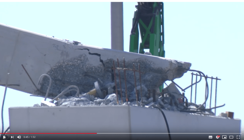
(f) I have repeatedly went over between your Frame049 and Frame057 and my observation are (1) bottom of 11 suddenly lost support and (2) Member 12 bent and its movement was similar in magnitude to the deck/9/10 and canopy/10/11. It is not possible with sufficient confidence to say which joint went first. To me the most important piece of information from your captured frames is Member 11 suddenly gave away. The apparent bending of the Member 12 could come from the local yielding near the vicinity of the joint with deck/11 by the concrete crushed/failed first but the embedded rebar were still fighting to hang on their position. Momentarily the local yielding of Member 12 produced a hinge which gave the impression the the Member 12 bent. After the collapse this yielding position or hinge was stripped off concrete leaving the rebar exposed.
Member_12_broken_end_at_support_zncugq.png


We all are interested in how this bridge failed. You have certainly done a great job using your skill to scan every possible clue from the video. I am just trying to make our assessment as watertight as possible. At the end of the day the collapse would be explained by the physics and none of the personal opinions would matter.

Sym P. le (Mechanical),

I also noticed the flexing of Member 12 and explained with Item (f) above. If the joint deck/11/12 failed first the damage joint could have concrete broken out and the remainder crushed resulting a local hinge formed momentarily during the collapse. Not saying my explanation is what had happened but just from the failure mechanism point of view such development should not be a surprise.
 
I edited my post of 7 Jul 19 04:44 concerning member 12 and added more material. I understand the need for clarity because "others are watching". Let me know if anything else needs to be fixed while I still have time to edit.
 
MikeW7 (Electrical),

I joined this thread 8 days after the FIU bridge collapse. It was already pointed out by many members here including myself that the Deck/11/12 joint was problematic and the collapse was due to a connection failure. This was before the serious cracks were known, construction drawings, NBC timeline, NTSB/OSHA reports/updates were available.

Since then with more information and data available to the public this forum has refined the our common consensus which is based on the members' contribution.

We are all prepared to look into other possibilities causing the collapse as long as evidence is available.
 
saikee119 (Structural) 7 Jul 19 14:39 said:
The apparent bending of the Member 12...
EDIT: In case anyone is wondering, the orientation of member 12 appears to be the same in frames 051-061, so the "bend" or "flex" of member 12 in frame 057 (compared to frame 049) that was mentioned by others is not an image-editing artifact.

In case anyone is wondering, frames 051-061 all show the same leftward "bend" or "tilt" of member 12 that is evident in frame 057, so it is not an image-editing artifact.
 
Mike said:
In case anyone is wondering, frames 051-061 all show the same leftward "bend" or "tilt" of member 12 that is evident in frame 057, so it is not an image-editing artifact.

Is there a link to these frames?
 
I think saikee119 summed it up well. The video doesn't show what failed first. It does show the deck and canopy failing earlier.

In the case of the canopy, it should be under little stress if member 11 is doing its job. In the case of the deck that would require massive and sudden failure of PT member. Highly unlikely and also I don't believe these were shown to have failed. Alternatively if member 11 or its connection failed and no longer was loading bearing the failure as shown is what you would expect.
 
Tomfh (Structural) 8 Jul 19 01:04 said:
Is there a link to these frames?
Here is a ZIP file of those frames, in two folders. One folder contains 640x360 frames cropped directly from the original video. The other folder contains the same frames enlarged to 2560x1440 using the methodology described at the end of my 7 Jul 19 04:44 post.

You probably won't be able to tell the difference between the two sizes if your image viewer automatically upscales and interpolates small images, a problem I discussed in my post dated 13 Jun 19 16:53. If your image viewer can be set to "view original size" or something similar, the larger images will appear as bigger versions of the smaller images with no interpolation artifacts - each pixel of the original image is expanded to 16 identical pixels in a 4x4 block.
 
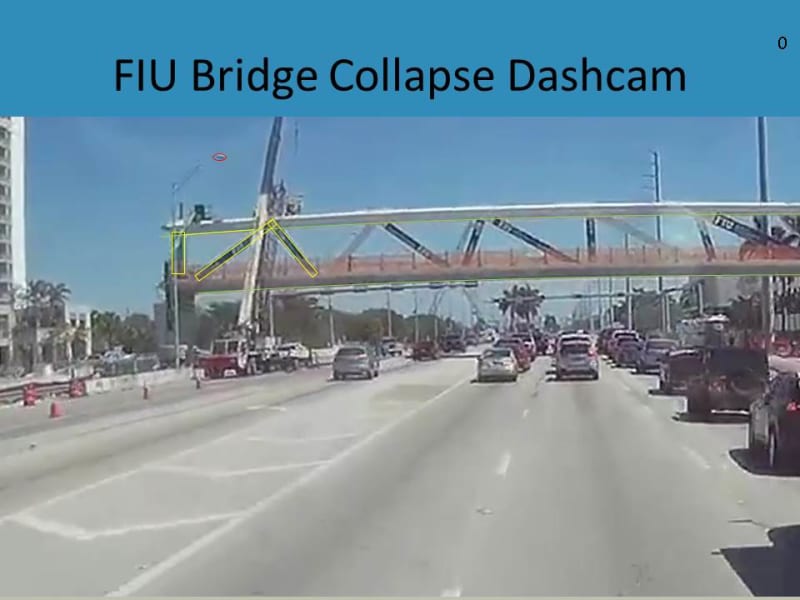
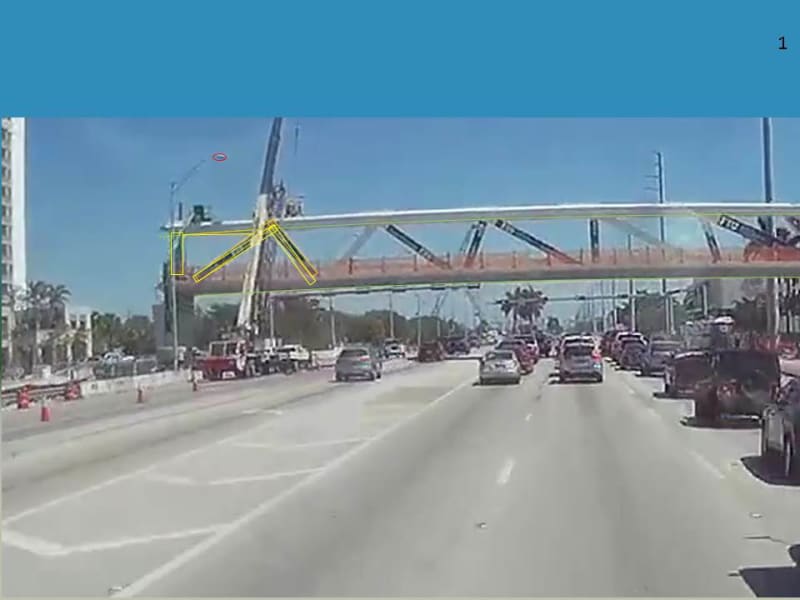
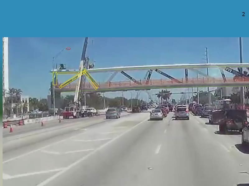
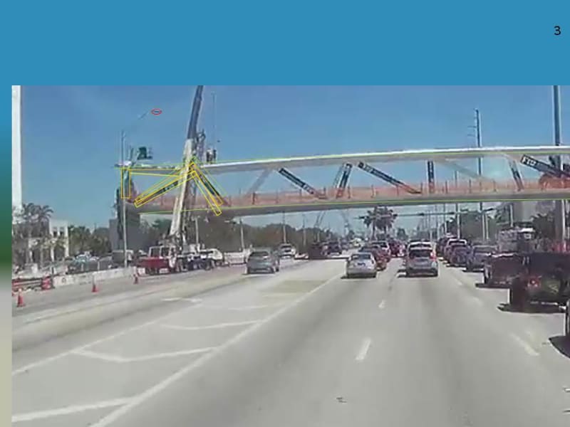
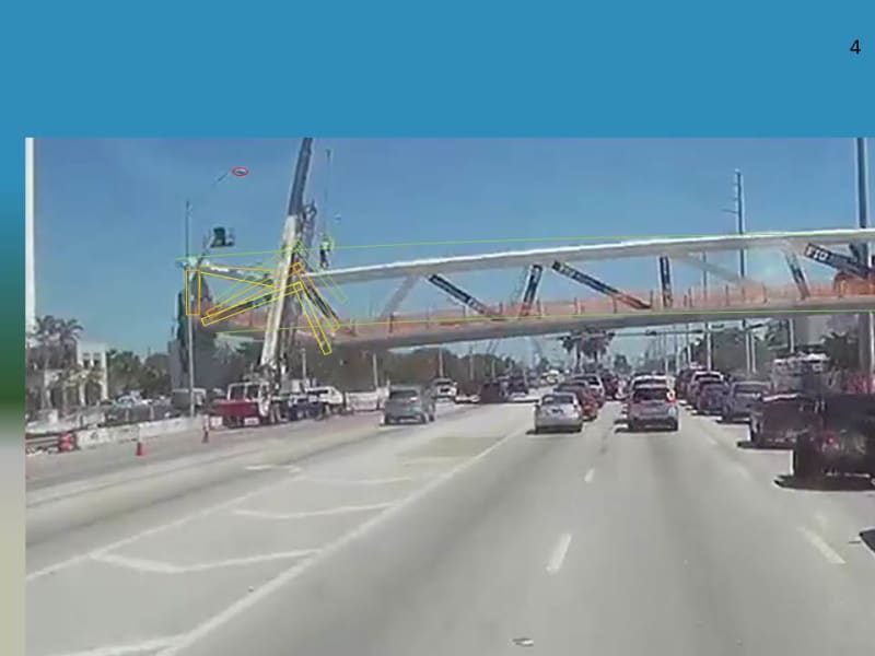
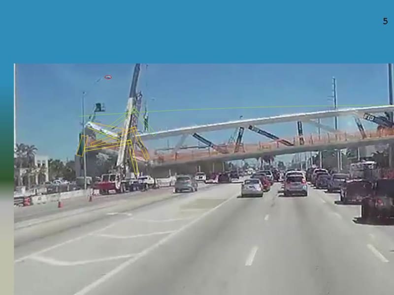
I did an analysis of the dash cam video a while ago, and abandoned it as more info came in. I have made .jpg files of the slides. dashcamanalysedfrompowerpoint.zip
Green outlines original position
Yellow outlines current position
Orange shows position on previous slide
(Before any movement detected)
Slide1_dbai0f.jpg

(angle in canopy at 10,11 angle between canopy and 11 remains constant angle between 10,11 changes)
Slide2_eunu5p.jpg

(continues as 12 appears to remain vertical)
Slide3_gyqfz2.jpg

(continues as 12 appears to remain vertical)
Slide4_jab9yu.jpg

(continues as 12 appears to remain vertical)
Slide5_zqxatk.jpg

(Finally 12 tips)
Slide6_sh74yq.jpg


SF Charlie
Eng-Tips.com Forum Policies
 
Thanks for posting these.

By that stage the collapse is well underway. Are there any earlier frames showing excess curvature?
 
Tomfh (Structural) said:
Are there any earlier frames showing excess curvature?
I was not able to detect any curvature, but the cherry picker arm in the foreground and the building behind make it difficult to make out 12, I admit.

SF Charlie
Eng-Tips.com Forum Policies
 
Tomfh (Structural) 8 Jul 19 02:19 said:
Are there any earlier frames showing excess curvature?
No. Frame 049 is part of an identical sequence 046-050, which is then followed by the 061-061 sequence. The time stamp in the lower RH corner of the traffic-cam footage was updating about every 0.4 to 0.5 seconds, so the phone was recording sequences of 10-15 frames for each update of the traffic camera. The video metadata says it was shot at 29.97 fps.
 
I went back and reviewed my analysis of the traffic cam footage, and the curvature in 12 is constant thru all the frames where 12 is intact, so it is not an artifact of the process, but probably an artifact of a wide angle lens on the traffic camera itself.
MikeW7 (Electrical) your work is awesome.

SF Charlie
Eng-Tips.com Forum Policies
 
MikeW7 (Electrical) said:
In my mind, the 7 July comment simply restates the 22 June observations in fewer words. Please help me understand why the pre-edited 7 July comment was criticized but the 22 June observations were not. The only significant difference I see between the two is the more detailed "blown off off the pier" versus "pushed off".

First your work on the video frames is awesome as SFCharlie has put it.

Secondly it wasn't a criticism but using factual information to back up deck/11/12 could have moved "before" deck/9/10 and canopy/10/11. I probably put in more basic information but that was for your benefit as you are not from the structural side.

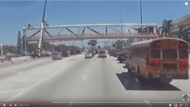
Your earlier 22 Jun post has the frames from a video captured by a "moving vehicle". It is not a like-to-like comparison to your 7 July frames which were extracted from a camera at a "fixed" position.

I must admit I didn't pay much attention to your 22 June when it first came out because many have already offered various comments on this video. It is funny different people from different background will pick different information off the same photos. Your 22 June frames are the prime example.

While you were preoccupied with Member 11 didn't deflect vertically my attention went to the horizontal extrusion, believed from Member 11,occurred in the 5 photos of Frames0074 to Frame0078 inclusively. This extrusion may have been distorted by the moving camera in the vehicle but it happened exactly when the bridge started to collapse and "disappeared" completely in Frame0079 and later when the angulation of the falling bridge would have pulled north end of the bridge inward to clear the pylon. Thus your photos reinforce my belief Deck/11/12 was the weakest point to fail first. The extrusion was the local breaking-up of concrete from the Deck/11/12 joint from a sudden release of stored energy from the overstressesg of materials. OSHA used the word blow out in the report.
 
saikee119 (Structural) said:
Member 11 didn't deflect vertically my attention went to the horizontal extrusion

I'm afraid that I don't understand how you're using the word "extrusion" in this context. Could you elaborate please.
I appreciate your experience very much, as I have none.
Thank You

SF Charlie
Eng-Tips.com Forum Policies
 
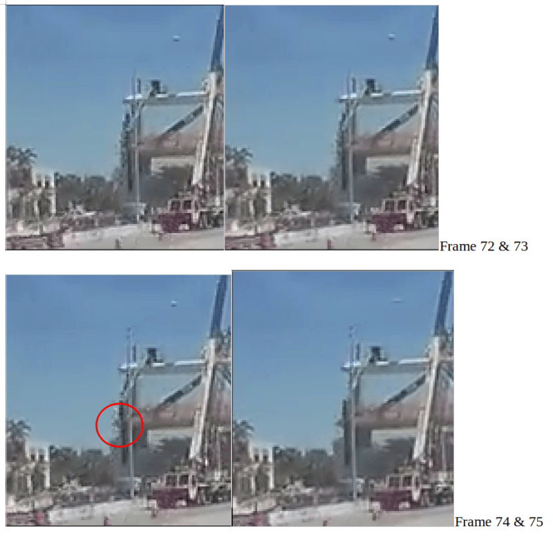
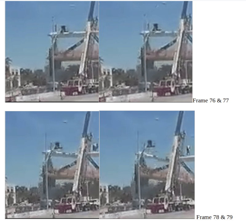
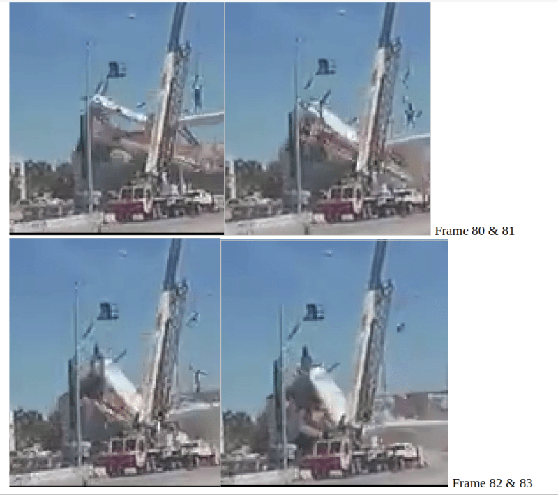
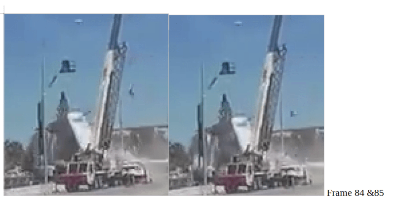
Mikew7 on June 22 post has posted the following frames which I cut off half for space saving listed below. The purpose of re-posting these photos is to show the side extrusion on the north side of Member 12 at the bottom of Member 11. Mikew7 has already gave a run down of the general events.

72_to_75_wmfzow.png

76_to_79_wsqqou.png

80-83_luxmj4.png

84-85_m7hevn.png


The extrusion on the north of Member 12 first appeared in Frame 74, remained visible in Frame 75, 76, 77 and 78. It can be said the extrusion disappeared in Frame 79, 80 and 81. Something similar, possibly from the broken off bottom section of Member 12, were sticking out at nearly the same level in Frame 82, 83, 84 and 85. Member 12 could not be viewed properly as it was partially shielded by the rear crane most of the time. From Frame 82 to 85 the dust and debris from the deck/11/12 joint breaking-up could have darkened some areas.

The deck could be seen resting on top of the pylon in Frame 72 to 82. Its departure progress from the pylon was recorded in Frame 83 and 84. Although the view of the deck was blocked by the front crane in the last Frame 85 it is known the deck final resting position was on the ground.
 
SFCharlie (Computer),

Some Forum members have already mentioned something were sticking out at the north side of member 12 during the collapse. It was generally interpreted as the deck/11/12 suffered a blow out at this position or some concrete was broken off but still retained by the rebar momentarily.

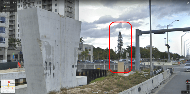
At exactly the same location of the extrusion, by that I mean something extruded out from Member 12, there was an evergreen tree at the background and so one can say the extrusion could be from one of its branches. However the size and times it appeared and disappeared in the video does suggest it could also have been a byproduct of the collapse.

The evergreen tree branches might have been trimmed when the Google Street View was recorded later and depicted below. It is between the empty pylon and the steel column for the traffic signs. This tree could be seen in all the frames above.


evergreen_tree_regni6.png


The evergreen tree at the time of collapse can be seen below.

tree_shape_at_collapse_gn0gsr.png
 
I had interpreted the rectangle to the left of member 12 and aligned with the front of the deck as the northwest corner of the deck. I think it appears as the truck moves from west of the deck to southwest of the deck. It does appear attached to the deck as it rises in line with the deck as the deck falls. To me, it appear to move with the deck as they slide off the pier.

SF Charlie
Eng-Tips.com Forum Policies
 
SFCharlie (Computer),

I would agree one possible explanation for the sticking-out object could be the northwest corner of the deck to an approaching vehicle from the west.

On balance the frames show the object more triangular than rectangular although it is harder to tell in the original video.

The bit difficult to explain is as a part of the permanent structure this object was able to disappear when the camera got closer.

It is also slightly thinner than the rest of the deck's edge, visible in different color and seemed too long without the temporary fencing attached.

 
I went back and reviewed the frames I had analyzed. One thing I noted is the appearance of dust on deck between the bases of 12 and 11 in the frames that show 12 starting to tilt. (small in the frame where 12 barely tilts and larger in the frame where the tilt becomes definitely visible.)
 
I just reviewed the timelapse of the bridge move. the temporary fencing ends at the south face of 12.
As the diaphragm tips south, the corner of the deck would also move south.


SF Charlie
Eng-Tips.com Forum Policies
 
Status
Not open for further replies.

Part and Inventory Search

Sponsor