Continue to Site

Eng-Tips is the largest engineering community on the Internet

Intelligent Work Forums for Engineering Professionals

  • Congratulations KootK on being selected by the Eng-Tips community for having the most helpful posts in the forums last week. Way to Go!

Miami Pedestrian Bridge, Part XIII 81

Status
Not open for further replies.

JAE

Structural
Jun 27, 2000
15,460
A continuation of our discussion of this failure. Best to read the other threads first to avoid rehashing things already discussed.

Part I
thread815-436595

Part II
thread815-436699

Part III
thread815-436802

Part IV
thread815-436924

Part V
thread815-437029

Part VI
thread815-438451

Part VII
thread815-438966

Part VIII
thread815-440072

Part IX
thread815-451175

Part X
thread815-454618

Part XI
thread815-454998

Part XII
thread815-455746


Check out Eng-Tips Forum's Policies here:
faq731-376
 
Replies continue below

Recommended for you


Greetings to all

Regarding the shims under the deck, in the RFP plans it only says " place plate shim" It appears to meaan only one. But they installed 4. This is an big error because this structure was analyzed as a continuous support under the deck. Is the shims are discontinous and they do not fall directly under the centerline of member 12, then the state of stresses under the diaphragm is nor as the one provided by the FE model. As built, the big force from #11 has no place to go under #12 and has to distribute itself lateraly thru the diaphagm to the 4 shims placed on top of the pier (passing tru the vertical voids creted by the big pvc pipes). Placing the shim under #12 the week of March 10 it was too late. It did nothing for practical purposes. Furthermore, in the plans I can not find a description of the shim. Is there any info in the docket about the shims or who decided on the 4 shims? This is another issue that may be combined with an already "mess-up" situation that did not help to avoid the failure.

Details, Details... My "modus operandi" is to spend long hours laying in the couch thinking in ways the structure I am designing can fail and what components are acting to assist. No calcs. Only thinking. After that, I harden the critical elements (which usually are just a few) like the connections: increasing the thickness of the steel plates locally, increasing the size of the bars or the number, increasing the strength of the concrete, etc.

Anyway, at this moment it can be assumed that the state of stresses in the connection #11-#12-Deck is unknown and can only be found using sophisticated non-linear prograns that account for cracking (with real cracks that separate elements). I know one of this programs that is used by engineers doing analysis of structures to resist explosions and design goberment facilities or lifeline bridges like the the Brookling Bridge. My recommendations is for the Gov to hire Weidlinger Engineers to analyze the failure.

Regarding testing, I remember the Battleship Iowa case. Everybody was blaming the sailor until the "Sandia o Los Alamos" testing facility found thru many tests, that if you rammed the packs with a big force you could cause an explossion. So, it is not dificult, but expensive, to set several true size samples of a 10"x10"x10" area of the end with #11, #12 and the deck; and apply sereal jbib jacks a test the situation. Any takers?
 
Agree. Placing the last shim under the center would not cure any cracking or restore any capacity in the diaphragm. Installed loose or without preload, the last shim might have prevented further damage to the diaphragm but could not help until it shared some of the load. Had they gone thru the procedure with jacks and such and lifted the diaphragm to level all ( now ) five shim packs, the new shim could have shared the load but at this stage, lowering the damaged diaphragm onto a level and uniformly supported surface would have caused realignment in the cracked diaphram much like restoring the PT in member 11, and probably caused more damage.
Too late is the correct phrase. Damned if you do and damned if you don't.
 
Samwise,

When it comes to PT, the girder section is not that simple. In these cases, you usually have to use software like Concise. The plane section and equilibrium equations that you refer to don't give you everything that you need. The truss means that you eliminate the tension stresses on the top at the ends of the span from the PT. You also have to remember that you don't have plan sections at the end of the span and a very high PT force. I think a truss in some regards does simplify the analysis and complexity but it also removes redundancy. Really, the only thing that is difficult to calculate by hand are the secondary moments on the members but it can be done with moment distribution. I started work without a computer on my desk and this what we did.

You still have cold joints with shear flow, a strut and tie model for the ends of the girder, web instability checks etc. So it is not necessarily as simple as you might assume.
 
One more comment.

To anybody that is not an structural engineer and it is only an inspector or contractor, the structure looks may fool them to believe that the deck act as a beam with a lot of capacity like your tipical bridge. Specially if they already know that the "stays" are fake. So, those in the meeting of March 15 (FDOT "accountant", INSPECTORS, contractor personel, FUI personnel, but not FIGG people) may have accepted the "no problem" becase they did not understand the importance of the truss action and the connections and they saw a "thick" beam cross section. Furthermore, they were in front of the "demigod" of bridge design. Who in that room can contradict the "almighty" FIGG? Was the arragement of the meeting fast and with few invitees on purpose to avoid the prersence of the "FDOT troublemakers"? Who knows?

I can tell you one thing, if Tom Andres or any FDOT structural engineer (District or Central Office) had seen the cracks (week of march 10) in photos, in person or have attended the presentation, the road would have beeen closed and 6 people would not have died.

Just trying to understand how the unthinkable happenned....
 
FIGG Computer Analysis
In the NTSB Report and during the meeting we see that FIGG did 4 computer analyses of the structure.
1) One analysis of the single independent span of 174 feet as it existed in place at Stage 3 and during collapse. There I find the north end member 12 defined as a diagonal and having the properties of a 21 X 34.5" section, which is correct. The term diagonal is applied to all web members.
2) An analysis of the complete two span structure titled "Longitudinal" something. That would only apply to the structure after complete.
3) Analysis under transport conditions. Has anyone seen the input properties of member 12 in this analysis?
4) Analysis under fixed end conditions with pylon and "pipe stays” in place.
So what is MCM talking about when they say FIGG incorrectly used the full completed pylon section in their analysis?
The use of properties of the full completed pylon is correct for the conditions 2 and 4 above and was not used in condition 1.

I am unable to confirm the section used for member 12 in 3) above - transport conditions. I can find input for deck members and canopy members but not for diagonals.
See beginning on pdf page 557.

I can find a table farther into the doc but because it seems to apply to members 1>11 and 14>23 I think it applies to the full completed structure. So I cannot confirm what was used for member 11 properties during transport.
From photos we know that member 12 was 21 X 34.5" during transport and failure. Not sure what a different property for member 12 in a computer program focusing on transport conditions would have to do with the collapse.
 
The Mad Spaniard said:
Who in that room can contradict the "almighty" FIGG?
Maybe BPA's Maria Kristina Acosta, it is a shame the NTSB did not interview her. While her boss Jose Morales described her has 'office staff' her cohort Carlos Chapman described her as 'Regular Inspector', the same has himself.
She has a Forensic background and a Mechanical Engineering degree. Link

There is a lot to take in. I was under the impression that Figg was unaware that the advanced cracking in the 11-12 node took place before the detensioning of the PT bars in member 11 but there is an email that shows they did know the photos taken at 3:16-3:17pm were taken before the detensioning. It boggles the mind to wonder what they were thinking by retensioning the #11 PT bars.

2 hours and 45 minutes (12:30pm to 3:16pm). That is all the time it took for the bridge to start failing, after it had been set. How does that not cause alarm bells to go off?
 
Earth, I can see where I am being misunderstood, but I am not saying that the structure as-is should have been analyzed as a prismatic section. I am saying that they used a complex system in the form of an open, strut and diagonal web for what, in a lot of ways, is an I-beam. Comparatively speaking, obviously, a constant prismatic section is far easier to design than the structure they implemented. Everything you are saying I realize would be a consideration in analyzing the "truss" bridge, which is exactly why I just wouldn't go there with concrete. Way too outside the wheel house for the material type.
 
The faux pylon and stays were tacky from the start, but in light of the collapse and the loss of life they seem a particularly unfortunate choice. I'd guess that functional stays and pylons would have been much more expensive, but suppose the faux counterparts had been omitted in favor of more effort and material in the primary structure. It can't have been a trivial matter to design the stays and pylons given that wind loading would control, so there might have been a substantial trade-off in favor of artistic factors.
 
Trusses Instead of Solid Webs? BY MARCO ROSIGNOLI May 2001


In a truss box girder, however, neither longitudinal nor torsional shear deformation can be neglected. Therefore, these effects need to be carefully analyzed.[sup]1[/sup]

Trusses Instead of Solid Webs?

 
Samwise,

I actually don't think a concrete truss is a bad idea. There are practical ways we can make it work. It has advantages like durability and reduced maintenance costs. It was just that the execution was wrong in this case. It is also unfortunate that it is so rare to have concrete trusses and this will scare people off of them but they do have a place.
 
Note to all

I believe I have said this before. The truss can be made safe with just a little bit more of concrete and rebar in the right locations (connections) and supports under member #12. I have no problem with this type of structure. It is ok.

However, this case will scare the hell of out of every owner (Sad). Except Spaniards. Remember that their national sport involves "playing with the bull".[smile]
 
I think this aired on "Engineering Catastrophes" on the Science channel the other day. Anyone see it? I missed it. Hoping for a rerun.

Some of that NTSB Board meeting gets pretty intense. Thanks for the post.

EIT
 
charliealphabravo said:
The faux pylon and stays were tacky from the start, but in light of the collapse and the loss of life they seem a particularly unfortunate choice. I'd guess that functional stays and pylons would have been much more expensive, but suppose the faux counterparts had been omitted in favor of more effort and material in the primary structure. It can't have been a trivial matter to design the stays and pylons given that wind loading would control, so there might have been a substantial trade-off in favor of artistic factors.

I agree with their tackiness. In our built environment there is often a role for function and style to go together. But it becomes particularly clumsy when you have items that are fake engineering solutions. Either make the engineering beatiful or add some superfluous form to the structure. But when superfluous form that attempts to mimic engineer is just bad architecture.

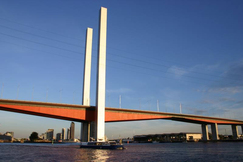
This bridge is the same:
Boltebridge_vw9tzn.jpg
 
I agree those towers are silly. Even my wife said when we first saw it, "What are those poles for?"

For those who don't know, that is the Bolte Bridge in Melbourne.
 
Interesting towers. At least they give ships an idea where one pier is while still far enough off for that information to be useful.
 
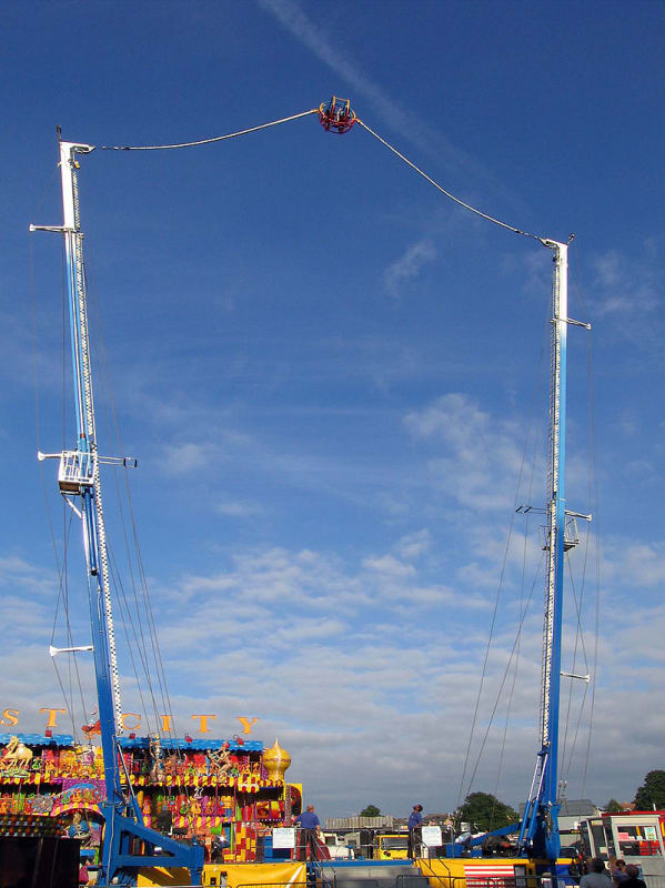
They should add some vertical windmills to the towers. At least it make more sense. Nice laminar air flow over the water. My personal aesthetic is to make the architectural components functional. However, I also think aesthetics are very important. I find completely utilitarian urban landscapes very depressing.

The pylon and stays are essentially a form of sculpture and artwork. We pay for public artwork and this really no different. That doesn't mean all public artwork projects are successful.
 
I'm thinking....

800px-Power_Shot_-_Reverse_Bungee_02_j6w4r0.jpg


Brad Waybright

It's all okay as long as it's okay.
 
A recent ENR article -

Quote: [blue]"“Despite the completed two-span model generating the largest forces, for reasons unexplained, the FIGG design exclusively used the results for the main span simple and fixed support models,” said Walsh."[/blue]

and

Quote: [blue]"The guide for bridge design, the AASHTO-LRFD code, speaks mainly to steel structures and had no specific guidelines for concrete truss bridges. In its recommendations, the NTSB asked that such guidance be added to the AASHTO-LFRD code. But engineers are supposed to make accurate calculations even when there is no specific code to lean on."[/blue]
 
Status
Not open for further replies.

Part and Inventory Search

Sponsor