Continue to Site

Eng-Tips is the largest engineering community on the Internet

Intelligent Work Forums for Engineering Professionals

  • Congratulations KootK on being selected by the Eng-Tips community for having the most helpful posts in the forums last week. Way to Go!

Miami Pedestrian Bridge, Part XIII 81

Status
Not open for further replies.

JAE

Structural
Jun 27, 2000
15,444
A continuation of our discussion of this failure. Best to read the other threads first to avoid rehashing things already discussed.

Part I
thread815-436595

Part II
thread815-436699

Part III
thread815-436802

Part IV
thread815-436924

Part V
thread815-437029

Part VI
thread815-438451

Part VII
thread815-438966

Part VIII
thread815-440072

Part IX
thread815-451175

Part X
thread815-454618

Part XI
thread815-454998

Part XII
thread815-455746


Check out Eng-Tips Forum's Policies here:
faq731-376
 
Replies continue below

Recommended for you

JAE (Structural)(OP)29 Oct 19 20:32 A recent ENR article - [URL unfurl="true" said:
https://www.enr.com/articles/48016-what-florida-br...[/URL] Quote: "The guide for bridge design, the AASHTO-LRFD code, speaks mainly to steel structures and had no specific guidelines for concrete truss bridges.]
Would anyone HAZARD a guess why?
Could it be the low demand for such a structure? (Hint: Zero )
Blimps to cross the Atlantic. (Hindemberg)
Kerosene lanterns for light to milk the cow in Chicago. ( Mrs. O'Leary )
Concrete Truss Bridge (FIGG )
 
And unfortunately the same ENR article stated:

ENR said:
The result was an underestimation of sheer interface demand at different nodes varying from 41% to 91%...

Oh well, what is an 'e' and 'a' among an engineer readership - supposedly we can't spell.
 
I have seen a few other people spell it as sheer but not very often. It is more like a sheer drop off on a cliff or sheer fabric (can see through). I think they are mixing up the meaning of the words.
 
Now THAT explains a lot. And even makes sense.
This bridge has been an illusion since concept. This points out how well that illusion worked.
The public was supposed to see a thin deck with pedestrians suspended by cable stays with a roof supported by crazy angled diagonals supporting the roof. SOLD.
The roof was so much smaller than the deck - so just a roof. The diagonals held the roof up so that is simple and can't be critical.
So if the construction personnel had walked on a hundred trapezoidal box girders with the PT in the bottom and saw some cracking in the deck at the end of a column just holding up the roof - what's the problem?
The illusion was so successful that it contributed to the failure.
The importance of the diagonals and their connections should have been the subject of about 2 hours in a pre construction meeting and a half hour every week. Devise a quiz and anyone not demonstrating the understanding of importance to be reassigned to paving overlay work.
Kudos #2 for the Mad Spaniard - the politics and how they influenced the decision (?) to not close the street. I'm thinking that is a home run there. (We watch baseball instead of trying to out run bulls).


NTSB Meeting - staff reporting - 49:00 or so
Showing 4 diagrams which represent the 4 analyses made by FIGG.
Note the "Fixed Pylon Mainspan Only" - shows the main span only with no back span. It also shows the Pylon cast full height and the faux stays in place. This can explain the terribly low shear results at node 11/12.
Have always wondered how the shear at the top of the deck could be so low at 11/12.
In the model they show, the stays are NOT faux - they will be found ( I am betting here ) to have considerable tension and are holding up a lot of the bridge weight.
This is a good idea - check the maximum load that could happen to the stays and pylon in bending.
It is a terrible idea to use for design of the main span of the bridge which must be self supporting for months without any contribution from the pylon and stays.
The very act of installing these pipe stays to a vertical surface and a horizontal surface with perpendicular bolts at both ends is gonna be tough. I see slotted holes in the future.
And I still would like to know they considered vortex shedding.
I suspect the contract for the pipes has been cancelled by now.

 
It seems unlikely the pipes can carry significant loading as there is little moment resistance in the pylon.
 
In my reading of the NTSB report, I did not see any discussions related to the design/build project delivery method and whether it could have contributed to the interactions between MCM and FIGG. In my opinion, design/build creates an inherent conflict of interest for the design professionals. The financial performance of the contractor implicitly effects future earnings of the design team. Does anyone know if closing the road would have had a negative financial impact on MCM? Did the project contain liquidated damages or were there incentives for early completion?
 
I think the "Fixed Pylon" analysis may have modeled fixed anchors with no dependence on pylon bending. I can't read the input. Do not know how to find pieces or nodes.
The back span pipes would have provided relief from moment in the pylon. Not all, but a significant amount.
Modeling the pylon for bending cantilevered 90 feet or whatever without stays to the north span would be unrealistic because the bending would have released tension in the south stays and reported lower loads than the stayed full length condition.
The "Fixed Pylon" model is not a realistic condition but it simulates worst case conditions for the pipe "stays" and maybe the pylon, and should draw load to the north end of the main span (pylon) because of the fixity.
EDIT I have to wonder if it was modeled with no dead load and stays in place - as if it had shores in place until the pipe stays were tightened. That would be impractical and unrealistic, because the structure will have dead load deflections in place when the pipe stays are installed. So realistically, only live load and creep will load the pipe stays. But the load reported for 11/12 sliding is too great for Live Load factored and adjusted for simple fixity ( that sounds like a contradiction ) at the pylon.
Thanks,
 
That's true after the bridge is complete - the analysis was for only the span and the pylon if I've understood what was written here.

"Note the "Fixed Pylon Mainspan Only" - shows the main span only with no back span. It also shows the Pylon cast full height and the faux stays in place. This can explain the terribly low shear results at node 11/12."
 
978kips shear demand at the node!? Where is the sanity in that. A first year engineer should be able to tell you that doesn't make sense given the unfactored dead weight alone.

(Sorry if none of this is new to anybody, I'm only loosely folling this thread. I just had a watch of the NTSB Board Meeting video.)
 
EARTH said:
I have seen a few other people spell it as sheer but not very often.

At university I did a project on automated asphalt crack repair. I referred to the "sheer length" of some roads needing repair (i.e. the roads are very long and there's a lot of cracks to fix).

When I got the paper back "sheer" was circled in red and marked up with It's spelled SHEAR!!!
 
There is a pedestrian bridge over the airport parkway in Ottawa, ON that was originally designed as a cable-stayed bridge, but the designers called for pipes instead. The use of pipes was heavily criticized, the designers were fired, and the new design used cables. This happened about 6 years ago.
 
What is Pcr in concrete column buckling?
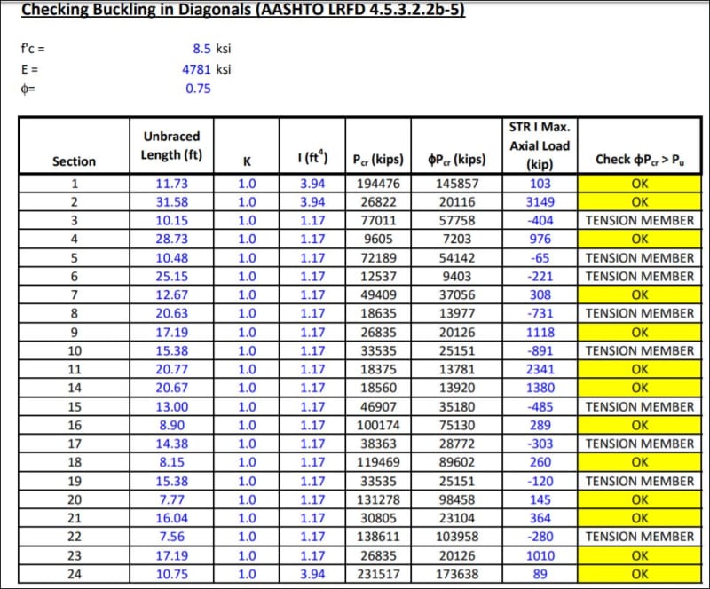
Help me, group. I am trying to find why there is a Pcr for a 21X24 concrete column that results in a stress of 36 ksi. Scan the attached pic from FIGG calcs pdf sheet 1128. They are checking buckling.
However they are doing it, member 11 gets a Pcr = 18375 kips. Yes - it says 18,375 KIPS.
That is 18375000/(21x24)= 36,468 psi. What kind of value is that? The concrete blew up at 8500 psi -
Does that mean the concrete can be stressed to that value before buckling is an issue?
If that is the case, it just does not look like a number that should be generated. Some analysis guy might use that for a divisor.
For whatever load case this might be, the axial load in member 11 is reported to be 2341 kips factored.
AASHTO_Buckling_Ck_iwjl3w.jpg
 
OHIOMatt said:
In my reading of the NTSB report, I did not see any discussions related to the design/build project delivery method and whether it could have contributed to the interactions between MCM and FIGG. In my opinion, design/build creates an inherent conflict of interest for the design professionals. The financial performance of the contractor implicitly effects future earnings of the design team. Does anyone know if closing the road would have had a negative financial impact on MCM? Did the project contain liquidated damages or were there incentives for early completion?
As a PE in Florida and someone that has been EOR on major projects like this, I can't point this out enough. Design-Build has its place but when oversight is delegated to a non-qualified party and price eliminates a required Peer Review by a pre-qualified firm on a Category 2 structure, something is really wrong and someone needs to be held to account.
 
Vance Wiley said:
What is Pcr in concrete column buckling?

P[sub]cr[/sub] is the Euler buckling load which is simply = π[sup]2[/sup]EI/L[sup]2[/sup] - it has nothing to do with material strength.

If you substitute in FIGG's values for Member 11 of: E = 4781 ksi; I = 1.17 ft[sup]4[/sup]; and L = 20.77 ft, I calc P[sub]cr[/sub] = 18,430 kips.

Vance Wiley said:
For whatever load case this might be, the axial load in member 11 is reported to be 2341 kips factored.

The load case is STRENGTH I.
 
I have watched some of the board meeting (about halfway through) and the one thing I can't understand is how did the FHWA's post collapse analysis have such a higher shear demand than FIGG's? Also fig had a model (2-span condition) which had higher shear demands, did they decide that model was no good? I mean if you had just used statics to determine the force at the node, I'm hoping that it would atleast be closer to the model that FIGG used (for FIGG's sake).

EIT
 
Vance Wiley (Structural)30 Oct 19 05:43
What is Pcr in concrete column buckling?

Thanks for the post.

Now we know of another place where we have a number for the #11 strut force in FIGG calcs. It can be used as areference despite the fact that may contain a large live load instead of the small construction load and it may refer to the completed structure. Using a 32° angle, the Strength 1 load of 2341 kips gives us a shear load of 1985 kips vs the 987 kips used in the connection evaluation.

FIGG had calculated adequate numbers in their analysis but they were never used. THIS IS NUTs!!!!
 
Status
Not open for further replies.

Part and Inventory Search

Sponsor