Eng-Tips is the largest engineering community on the Internet

Intelligent Work Forums for Engineering Professionals

  • Congratulations waross on being selected by the Tek-Tips community for having the most helpful posts in the forums last week. Way to Go!

Miami Pedestrian Bridge, Part XIII 81

Status
Not open for further replies.

JAE

Structural
Jun 27, 2000
15,432
0
36
US
A continuation of our discussion of this failure. Best to read the other threads first to avoid rehashing things already discussed.

Part I
thread815-436595

Part II
thread815-436699

Part III
thread815-436802

Part IV
thread815-436924

Part V
thread815-437029

Part VI
thread815-438451

Part VII
thread815-438966

Part VIII
thread815-440072

Part IX
thread815-451175

Part X
thread815-454618

Part XI
thread815-454998

Part XII
thread815-455746


Check out Eng-Tips Forum's Policies here:
faq731-376
 
Replies continue below

Recommended for you

I can confirm the 571 kips is way too low.
The value of 571 Kips for interface shear at 11/12 is less than the vertical end reaction contributing to truss action under unfactored dead load. (Less than the total end reaction minus half the first bay of canopy and half the first bay of deck).
Where did the 571 come from?


Vance Wiley said:
Where did the 571 come from?

From here:

MCM post-collapse NTSB submittal document #628566 said:
...FIGG reported (571 kips) in its 90%, Final and RFC design calculations for the Simply-Supported case.

And to bring the 571 kips into context, from MCM submittal, page 96:

capture_fiu3_qiatxs.png
 
I have become confused about the timeline of the cracking that took place on the day the bridge was set on the pylon and the PT bars detensioned.

According to phone records, VSL - Kevin Hanson is on site at 6:04AM on March 10, the day the bridge is set on the pylons.

At 2:00PM VSL - Kevin Hanson informs SAMUEL NUNEZ, Project Manager Structural Technologies VSL, that they are just getting started.

At 3:00PM VSL - Kevin Hanson informs SAMUEL NUNEZ, Project Manager Structural Technologies VSL, that they don't have hydraulic oil for the equipment and asks for the grade required.

At 3:09PM SAMUEL NUNEZ, Project Manager Structural Technologies VSL, responds that the grade required is AW32.

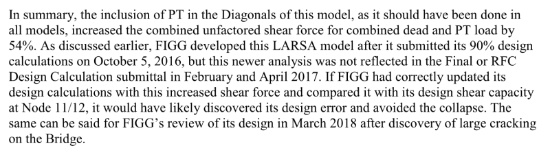
At 3:16 the advanced cracking in the 11/12 node & deck are photographed.

At 6:30OM VSL - Kevin Hanson informs SAMUEL NUNEZ, Project Manager Structural Technologies VSL, that they are done detensioning 2 & 11.

According to emails from Jake Perez at BPA & Alan Phipps of Figg, there wasn't any incremental procedure for the tensioning or detentioning of individual bars. And according to Jake Perez at BPA, their records show these actions were performed as single stressing and later detressing per bar. In other words not 50kips on (A) then 50 kips on (B), etc.

From the interview of BPA's PT inspector, as best as can be gathered, the minimum time to perform one PT operation is at the very least 15 minutes.

So were the cracks in the north end of the bridge there before the detensioning or after the detensioning?

Figg made the, hard to swallow argument that no peer review was required to restore tension to the PT bars in #11 because they had been previously in that "statistical state". The problem with this argument is that Louis Berger's peer reviewer, Dr. Ayman Shama, in his interview with the NTSB, had stated that his certification of Figg's plans was, in part, dependent on a condition that the massive compressive forces in the 2 & 11 truss members, created by the PT bars be detentioned, as soon (very soon) possible. Thus restoring the tension to the PT bars in #11, nullifies the peer review.

It seems very apparent by what transpired that everyone who attended the meeting on March 10, 2018, that the cracking was a symptom of detensioning but the timeline leaves a great deal in question. The interview with Alexis Molina, of Corradino Group, the certified PT inspector hired by BPA, devolves into a "Who's on First?" sequence, when the NTSB tries to nail down when the cracks first appeared. Never the less, starting on page 21 of the interview, it seems to be the case that the advanced cracking occurred BEFORE, the PT bars were detensioned; highlighting Dr. Shama's concern.

If the cracks existed before the detensioning, then Figg's retentioning plan wasn't restoring thing to a previously more stable "statistical state" but was actually recreating the conditions that precipitated the initial damage.
 
Ingenuity (Structural)24 Oct 19 20:48
Quote (Vance Wiley)
Where did the 571 come from?

In page 1387 (Section 10) of FIGG's calcs (LUSAS results) and from simple span analysis of (DL+ PT) the number 570.6 kips appears in the Fy resultant. However, in page 1283 (Secion VII) the rebar in the connection 11-12 to deck is calculated by Mr EDL and checked by Mr. MF using a 987 kips force (which is still low). The interesting thing is that in page 1298 (a few pages away) Mr. WDP (checked by Mr. MF) uses a force ("from Eddy") of 1521 kips to evaluate the nodal zone.

So, is it 987 kips or 1521 kips? Is 1521 kips a service load or a factored load? Because 987 kips appears to be a factored load... Looking at Mr. WDP calcs, it seems that the 1521 is a service load comb. So the factored load may (ball park and conservatively) about 1.25x1521 = 1901 kips (vs 987 kips)

One more mistery...
 
I have to say that the conclusions of the NTSB (Figg used in the design lower demand and did not request in the plans the roughening note) were obvious many months ago when the plans and calculations were available to the public from FDOT (free) and FIU (for $35.00), respectively.

Oh, well...
 
Thank you for pulling that together. It does not paint a pretty picture.
The 1901 kips you present is in line with the bar chart comparing node demands created by NTSB.
 
Vance Wiley said:
Using concrete in bending, the old days used allowable compression stress as 0.45 F'c which was a SF of 1/.45 = 2.22. So yes, LRFD works closer to the edge.

What was the factor on reinforcement? (which is of course the relevant factor for bending)

For failures controlled by concrete strength, the limit state factor is usually around 0.6 with a load factor in the order of 1.35. Equivalent FoS of 2.25, quite comparable to your 2.22.
 
The Mad Spaniard said:
In page 1387 (Section 10) of FIGG's calcs (LUSAS results) and from simple span analysis of (DL+ PT) the number 570.6 kips appears in the Fy resultant. However, in page 1283 (Secion VII) the rebar in the connection 11-12 to deck is calculated by Mr EDL and checked by Mr. MF using a 987 kips force (which is still low). The interesting thing is that in page 1298 (a few pages away) Mr. WDP (checked by Mr. MF) uses a force ("from Eddy") of 1521 kips to evaluate the nodal zone.

Are those the original calculations of the bridge from FIGG? I have looked for them in the several links or repositories that have been provided in these threads, but I don't find them (at least any document with such amount of pages).

Could you tell us where they can be found or downloaded?

 
@Vance Wiley: "You don't get off that easy...."

You're right, LRFD is a straightforward concept. Thanks for the explanation.

If you ever have a question about hydraulic grade lines.....
 
It's too bad that the NTSB meeting apparently "barks up the wrong tree" about using the results from the simple span (main span) model rather than the final bridge model.

The problem doesn't seem to have been about using the main span-only model. After all, the bridge failed in a simple span, main span only configuration. So a simple span model is appropriate for that stage. And has been noted, progressing in the bridge construction (post-tensioning aside) would not have substantially increased the shear forces at the failed node. (Correct me if I'm missing something there). Certainly not double. The 570-600k demand being so different from the final bridge model should have raised flags.

It seems to be that the issue isn't which model was used, but that the simple span model seems to have been used incorrectly (to determine the demand forces to be counteracted). Per M&M's explanation, potentially software user errors. Or even if that's not the case, results that seem to not have been back-checked (e.g. by hand calcs).

The black box and insufficient oversight strike again...

----
just call me Lo.
 
Lomarandil said:
It seems to be that the issue isn't which model was used, but that the simple span model seems to have been used incorrectly
Regardless, it seems that one should have used the worst case as the design basis, right?

Brad Waybright

It's all okay as long as it's okay.
 
The model matters because the model FIGG used for their calculations, the simple span, overestimated the dimensions of member 12 and ran the calculations as if the backspan was partially in place. FIGG never properly accounted for the forces in the structure when the main span was supported with no contributions from the backspan. MCM’s analysis of FIGGs work states (page 92-93):

In the first model, Member 12 has the cross-section properties corresponding to the large (full) Pylon, even in the Simply-Supported stage prior to the erection of the Back Span and full Pylon. This indicates the results from the first model for Member 12 may be unreliable for the construction stages prior to integration of the Main Span and the Back Span.

I read this as the simple span model overestimated the dimensions and thus the capacity of member 12, amount other errors.
 
What? Oh my GOD! The extent of misunderstanding of the stages of this construction and the structural significance thereof by the people creating it is astounding.
This is like a game of Wack-A-Mole -- just as I begin to rationalize how we got to some place in this design process, something more startling pops up.
Can anyone confirm the MCM statement from the calcs?
We knew from the statement of the EOR at the March 15 meeting that help from the backspan was on the way. That help was to be in the form of more concrete at the pylon thru the bridge and the continuity reinforcing from full length PT forces thru the canopy, which was intended to allow the thrust from member 14 to act in resisting the thrust from member 11. I question whether the PT in the canopy can effectively work at the deck level and for this purpose full length PT at the deck level would have been more effective and solved other problems also, but it is a viable concept. The problem is that concept apparently completely masked the importance of Stage 2 demands, and everyone was looking beyond Stage 2 and to the Grand Opening.
Lo - this pertains to your post as well.
 
What I know about hydraulic gradients is it flows downhill and Friday is payday.
An ME - a good friend - said once maybe 40 years ago that he liked to see/use/design to a "half pipe" - I have never understood the intricacies of that phrase. I presume it means leave somewhere for the air to vent, size the pipe for flow and grade to do that, and all will be good. I can't ask him as he has passed on.
Am I in the ball park here? I remember Reynolds number, V-notch wiers, and a few things like that. Not enough to design them - just the general principle.
Any words of wisdom beyond "stay out of this business if that's all you got"?
Off topic - yes. I apologize in advance.

 
Yes, the final design details should have been based on the worst case of all stages of construction.

What I don't understand is how would the back span have alleviated the issue. The only think I see the back span doing is restraining longitudinal movement of the main span. NTSB correctly stated that there was no way that retensioning the Member 11 rods would bring the structure back to it's pre-cracked state. Concrete doesn't have an elastic range; it cracks and stays cracked. All the stresses and deformations were locked in as soon as they allowed the main span to simply support itself. That tells me that the most critical condition to evaluate was a stand-alone main span, simply supported.
 
Vance, I’m trying to find the calculations you asked for in the reports. The dimensions of member 12 are mentioned in MCM’s analysis of the collapse but I am looking for confirmation of this in FHWA report. Starting at page 76, they go into FIGGs use of computer modeling to analyze forces and capacities at the various node during the different stages of construction. But FHWA never addresses the dimensions of member 12 as used for FIGGs various models/calculations. The only place I am finding this information (it may be mentioned elsewhere) is in MCMs analysis. On page 95 of MCMs report, it looks at FIGGS LARSA model:

First, the cross-section assigned to vertical Member 12 is 28 square feet, which is much larger than its actual cross-section of 5.03 square feet at the time of Main Span transport. Given this large difference in cross-section, the load effects reported for Member 12 by this model are not expected to be accurate. Second, the PT load effects reported from this model only include the effects of PT applied in the Deck and the Canopy, not the Truss. PT in diagonal Member 11 (or any other diagonal) was not included, the application of which would have increased the axial and horizontal shear forces in Node 11/12 by hundreds of kips. Third, the model did not include the construction live load of 20 psf specified by FIU’s Design Criteria, which would have again provided even higher design loads.

While the construction plans outline 4 distinct stages of construction, it seems like there was an intermediary step between stage 3 and 4 whereby they poured the pylon for the backspan adjacent to the existing pylon/member 12. This was the pour that the EOR was recommending in the March 15th meeting, because it would help “capture” the 11/12 node and provide more support to 12?
 
Vance…

I bring nearly four decades of public infrastructure design to your question. You are correct that it's most common to design "gravity flow"/"open channel" pipelines such as sewers and storm drains to flow no more than half full at peak flow, at least for smaller pipes. There are several reasons for doing so, including the fact that peak flows are statistical, not deterministic, so designing for half full provides some room for flows that exceed what we think the peak is. This is especially true in small pipes where slug flows don't always behave as we predict. In larger pipes, where peak flows are less extreme compared to the average, many agencies allow designing for maybe 2/3 or 3/4 full at peak flow. (Water transmission and distribution pipelines are almost always designed for pressurized flow, which means the pipes are full.)

Also, back in the pre-computer days, doing detailed hydraulic calculations for open channel flow in pipes was a pain except at half full and full. Those are the only two flow depths for which it is easy to calculate the flow area and wetted perimeter. All other depth ratios (depth of flow divided by pipe inside diameter) require an iteration to solve for it, or scaling a pipe capacity chart, or using a specialty hydraulic slide rule. (If you pick a depth ratio and solve for diameter or flow capacity, it's a direct solution, but we sometimes start with flow and diameter and solve for depth ratio.) Actually, I could solve this problem on my HP-34C calculator as early as 1979 because of the calculator's built in SOLVE function. However, it was slow. Now I use a SwissMicros DM42 or Thomas Okken's Free42 simulator as get results virtually instantly.

Fred

==========
"Is it the only lesson of history that mankind is unteachable?"
--Winston S. Churchill
 
Lomarandil is right. The probable cause seems to have been black box user error (software analyst using "method of slices" at the interface instead of slightly away from the interface) and a failure to check black box output against a ball park, back of the envelope, hand calc.

Regarding the LUSAS software, I know software makers have no liability, and I have zero experience with LUSAS, but this method of slices at an interface seems like a problem.

Regarding Figg's 2,000 or 6,000 or whatever pages of documents. That is a big part of the problem also. No EOR can provide adequate checking or oversight of all of that garbage documentation.

Same goes for the Figg's fragmented design team. You have a self identified stress analyst emphasizing that he is an analyst and not a designer. You have an engineer saying I only designed the substructure, you have an engineer saying I only designed the back span, you have an engineer saying I was the principal engineer for the superstructure but I just used the loads that so and so analyst gave me.

I feel for these guys (and gals), because we can all make mistakes, and when I used to work in large design firm offices, these issues of over-reliance on software, lack of mentoring and oversight, and fragmented design teams were common in the environments that I worked in. I think they are common in a lot of offices, unfortunately, and combined with budget and schedule pressures, and they are a recipe for disaster.

The real tragic error in this case was the failure to realize the seriousness of the cracks and act decisively during construction.
 
Status
Not open for further replies.
Back
Top