Eng-Tips is the largest engineering community on the Internet

Intelligent Work Forums for Engineering Professionals

MITC4 Plate Bending Elements 3

Status
Not open for further replies.

DCBII

Structural
Apr 15, 2010
186
0
16
US
I'm a full time engineer, but I've put together a sort of hobby computer program that does basic finite element analysis to help me learn how it works. I've been trying to add MITC4 elements for linear analysis (nothing too fancy) but I'm having some trouble. This is my first time creating isoparametric elements, so I'm learning.

I've modeled a 10' wide x 20' tall x 1' thick concrete rectangular wall panel (E = 3823 ksi, nu=0.17) fixed on on four sides with a uniform surface pressure of 250 psf. I've meshed it incredibly fine with 6"x6" rectangular plates.

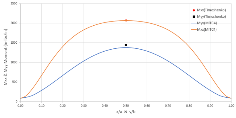
The shear stresses my model is calculating are spot on with values published by Timoshenko in "Theory of Plates and Shells", but the bending stresses that are calculated are about 15% smaller. The displacement calculated at the center of the panel is also slightly larger (~10%) than Timoshenko predicts. I've plotted contours and the displaced shape and the shape of the bending moment, and they both look correct. Only the magnitudes appear to be slightly off. The excess deflection and low moments make me think my flexural stiffness is too low, but my stress-strain matrix [Cb] is the easiest matrix to calculate and I've checked it multiple times.

I've calculated my stresses as [Mx, My, Mxy] = [Cb][d], with calculated at the 2x2 gauss integration points (+/-0.5773). I then extrapolated those stresses to the nodes using the shape functions. The extrapolation made very little difference with such a fine mesh, as the stress is nearly constant over the plate's area at locations of maximum moment. I don't think my extrapolation is the problem.

Any finite element geniuses out there with an idea what might be going on here? Do MITC4 bending elements require me to mesh even finer? My slow personal computer might blow up if I do. That seems like extremely poor convergence.
 
Replies continue below

Recommended for you

FEA way:
PyNite's current rectangular plates do not support uniformly distributed loads at this time, but these MITC4 quad elements will when I finish implementing them. For now I've been approximating uniform pressures on the rectangular elements using nodal forces, and the results match the Timoshenko solutions for the problems I've tested. They actually match better than the MITC4 elements, but based on this discussion, I believe that's because they are neglecting transverse shears like Timoshenko does.

nlgyro:
I forgot to thank you as well. Very insightful posts. Thank you.
 
Could you share a formula or code to convert pressure to equivalent nodal forces for these elements ? It would be very useful to me.
 
It's a bit of a process, rather than a closed form solution. The code for this is already in the "Quad3D.py" file on that link I sent you. Look at the "fer" method in that code and the methods it relies on.

Essentially the process for obtaining the force matrix is:
[ol 1]
[li]Identify the gauss points and weight factors for numerical integration. For a 4 noded quad, the gauss points are +/- 1/√3. In other words: (0.5773, 0.5775), (-0.5773, 0.5773), (-0.5773, -0.5773), (0.5773, -0.5773). The weight factors for each of these points is conveniently 1.0 for a 4 node quad, so they drop out of the solution.[/li]
[li]Form the shape functions (sometimes called interpolation functions) into a matrix that relates them to the out-of-plane translation degrees of freedom. This is the [Hw] matrix in my code, and it is a function of the natural r, s coordinate system for the element. The (r, s) points to evaluate it at are the gauss points.[/li]
[li]Calculate and multiply by the determinant of the Jacobian matrix, which is also a function of (r, s). This matrix essentially relates the (r, s) natural coordinate system to the local (x, y) coordinate system.[/li]
[li]Multiply the matrix obtained thus far by the pressure.[/li]
[li]Repeat and sum for each gauss point[/li]
[/ol]

In my "fer" method I multiply by the negative of the pressure, because PyNite's solver is after the reaction matrix rather than the force matrix itself.

When I get done implementing this I plan to post the derivations in a Jupyter Notebook with the program.
 
DCBII,

I did not know that PyNite was your repository. Great code, I have been referring to it heaps. And great name as well. I'll give it a star on github.
 
Thanks. It's been quite a project, but fun and educational for me. Still needs a lot of work and my amatuer FEA and Python skills show through in some places. I too found the textbooks difficult to follow and often full of errors. Having multiple books to compare to each other helped a lot. I really appreciate everyone's help on this forum too, and a few contributors who have helped me through a few points where I've been stuck.
 
Based on the responses above I was very curious to see how the moment distribution for the MITC4 element compares. So here goes:

2020-10-11_174545_ai3ylo.png


The peak bending moment for both Mxx and Myy occur at mid-span (as predicted by Timoshenko) and the moment magnitudes compare well with Timoshenko.

IDS in his post on 5 Oct 20 11:55 makes a valid point that the series expansion values published by Timoshenko for various b/a ratios are done with a poisson ratio of 0.30.

In the absence of a closed form solution for a moderately thick clamped plates with carrying uniform pressure loading, I whipped up a 8-noded shell FEM with the same dimensions/loading/properties as the original problem. Now convergence studies on the mesh have been done for the 8-noded model so the results for the 8-noded model would be base-lined against the MITC4.


2020-10-11_212303_jeqyml.png


As you see the Max Mxx and Myy for both model peak at their respective mid-spans and the peak magnitudes are identical (diff < 1%)
Timoshenko's values for Myy are higher than QUAD8 (8-noded FEA) & MITC4 results by ~5% and the Mxx values are identical (< 1%)

In all the values for MITC4 compares very well against QUAD8 and Timoshenko.

The peak deflection from the QUAD8 model is 0.00180in vs MITC4's 0.00176in a difference of ~2%.

So essentially for the mesh size that you have chosen of 6in/element, the MITC4 does a fantastic job!

Stress Convergence:

Now when talk about stress convergence MITC4 suffers for the same problems as do most 4-noded first order elements. The loading on the model generated a thro' the thickness Mc/I. MITC4 being a linear element will struggle to predict the in-plane strains/stresses for a moment varying along its length. So even using the option of shape functions to extrapolate the centriodal results to the nodes will not work as strain/stress along the length of the element for a varying moment is constant. Other solvers handle this defect with their 4-noded element using cubic-bending correction. As shown in my earlier post, this method works very well in the current scenario. But MITC4 does not posses this feature at-least from the documentation I have seen. But if reading element stresses directly from the model is your object of interest then you're in for the long-haul as MITC4 will take an extremely fine mesh to converge for thro' the thickness Mc/I stress.
 
IDS - They are the same as what the OP has described in his first post. All my models were done with nu=0.17, a=120in, b=240in and all edges fixed (Tx=Ty=Tz=Rx=Ry=Rz=0)


The moments are not zero at the edges.

What has been shown in the above two graphs are the variation of the bending moments Myy and Mxx along the short edge(a=120in) and long edge(b=240in) respectively. FE-model has X-axis is along short edge(a) and Y-axis is along long edge(b).

Parametric values (x/a) and (y/b) are used along the horizontal axis of the graphs. Location of moment peaks are as per theory. Mxx at mid-span of long edge and Myy at mid-span of short edge. Zero values are noticed at vertices (0,0) (1,0) (0,1) and (1,1) (using parametric values to identify vertices) which again is expected per theory.
 
nlgyro:

Are those most recent plots you posted "smoothed"? What does the plot look like unsmoothed? Does it look more like a step function? After looking into it further, I think the MITC4 element may be reporting center stresses at the corners, which explains the divergence at the supports. At the supports there's no adjacent plate to average the center stresses with.
 

Quoting:

> Are those most recent plots you posted "smoothed"?

Yes

Quoting:

> What does the plot look like unsmoothed? Does it look more like a step function?

That's a no brainer right?? unsmoothed (Un-averaged) plots are elemental data across the entire element and would resemble a step function when plotted.

Quoting:

> After looking into it further, I think the MITC4 element may be reporting center stresses at the corners, which explains the divergence at the supports. At the supports there's no adjacent plate to average the center stresses with.

Has been discussed and reported in the previous posts. Explains the reason why the MITC4 performs badly for through the thickness Mc/I stress. As you have coded the element can you post the nodal internal moments and the corresponding elemental centriodal values at any of the four vertices for the problem you had defined in your first post?

 
DCBII:
I trying to solve a plate problem using FEA. I need your help. I am trying to solve a simple plate problem. Will you be available to help me? I can commensurate your help.
 
Shell elements seem to be the most challenging to formulate. What is the conclusion regarding the MITC4? The reason I ask is that we are looking to try some of other element formuations for the MYSTRAN project (which is an open source solver with similar I/O as Nastran). Also, is there an 8-node version?
 
upuri1213:

I don't have a lot of spare time at the moment to help. I may be able to point you in the right direction if you describe your problem.

ESPcomposites:

Shell elements are challenging to formulate. I've found the MITC4 to be a good element so far, except when calculating stress results at plate corners. The center stresses and nodal force results are very accurate however. It also converges quickly with a fairly large mesh. What drove me to use it was that there are closed-form equations for the element freely available in "Finite Element Procedures, 2nd Edition". That book also gives formulations for an MITC8 element, but you'll have to dive a little deeper into the math.

One user of PyNite has found erroneous results when they skew the mesh under certain conditions, but when I skew the mesh I can't seem to produce the same error. I've been working to debug the issue (#78 in the repository), but it is elusive and proving to be difficult to identify what's causing it.
 
Status
Not open for further replies.
Back
Top