Hi. i have ran a modal analysis for an integral gear 3 stages compressor skid. the speeds of two rotors are 29121 and 42460 rpm respectively and motor speed is 3000 rpm. but the results was disappointing, there is almost 40 natural frequencies in the range of 10 percent lower and higher than rotors speeds which is not acceptable based on API. did anyone have the same problem? what should i do now? this amount of frequencies is natural?
Navigation
Install the app
How to install the app on iOS
Follow along with the video below to see how to install our site as a web app on your home screen.
Note: This feature may not be available in some browsers.
More options
Style variation
-
Congratulations TugboatEng on being selected by the Eng-Tips community for having the most helpful posts in the forums last week. Way to Go!
You are using an out of date browser. It may not display this or other websites correctly.
You should upgrade or use an alternative browser.
You should upgrade or use an alternative browser.
modal analysis of centrifugal compressor skid
- Thread starter cirus76
- Start date
- Status
- Not open for further replies.
GregLocock
Automotive
500 Hz or so? Yes that is a ridiculously high modal density in that 20% bandwidth for a supposedly rigid structure about the size of a car.
Cheers
Greg Locock
New here? Try reading these, they might help FAQ731-376
Cheers
Greg Locock
New here? Try reading these, they might help FAQ731-376
- Thread starter
- #3
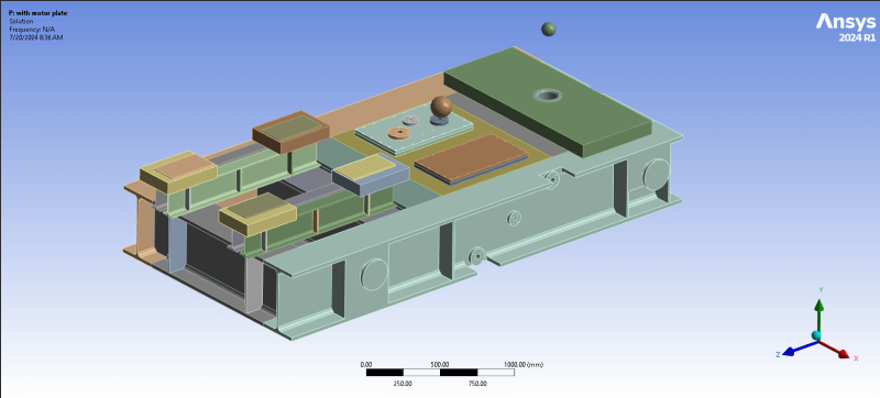
yes 500 HZ and 700 HZ. yes it is, i think one of the reasons is that the oil tank is designed through the skid and tank walls are reducing total stiffness. but beside that, the beams(H-500) webs are also vibrating. so you say there is something wrong with my analysis? i attach my skid picture.

GregLocock
Automotive
Have you looked at the mode shapes? Have you done a real life modal analysis on a similar skid?
Cheers
Greg Locock
New here? Try reading these, they might help FAQ731-376
Cheers
Greg Locock
New here? Try reading these, they might help FAQ731-376
jeyaselvan
Mechanical
What about your boundary conditions for the structure? Have they been adequately represented? As Greg suggested, did you have a look at the mode shapes? possibly lots of local modes, which may not be of concern !
- Thread starter
- #6
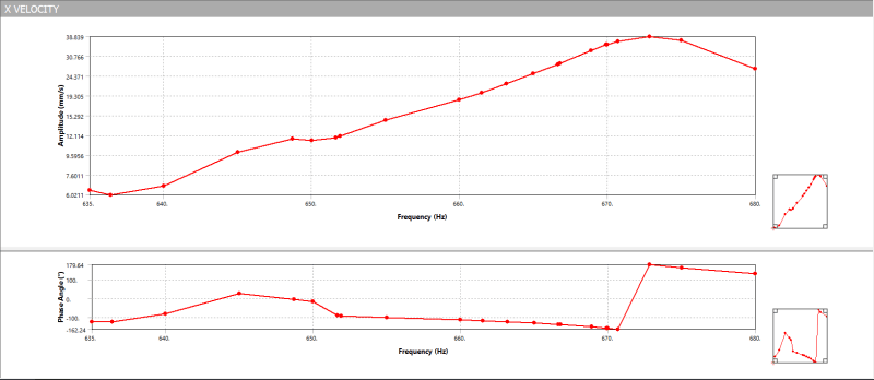
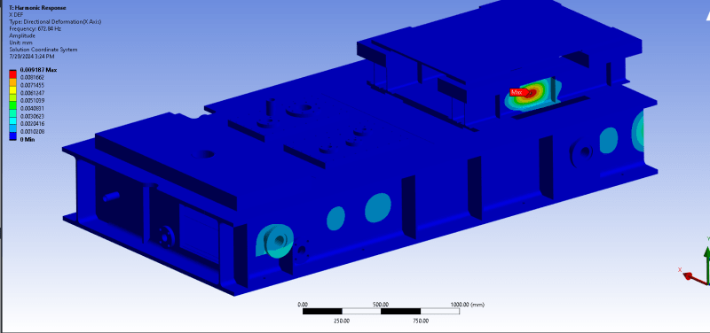
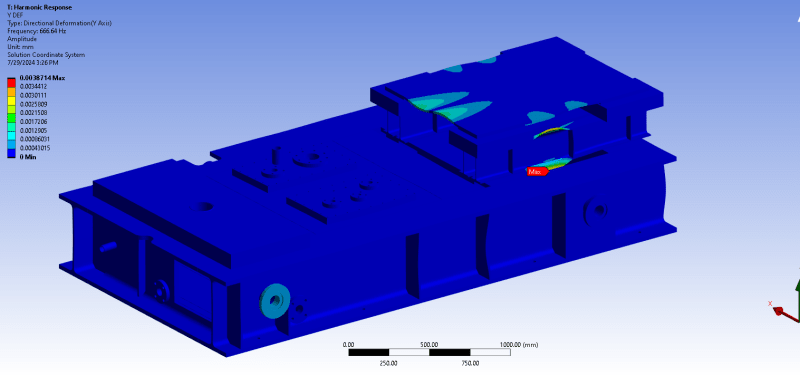
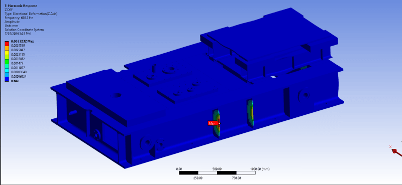
no i didn't do real modal analysis, just in Ansys workbench. yeah i have seen mode shapes and they are not in critical area like motor base plate or compressor base. they are mostly in stiffeners or beams webs. i also perform a harmonic response analysis and deformations amplitude are way under ISO 10816 limits but velocity is not. my question is what kind of vibration can i ignore? how should i judge?( i attach deformation and velocity response in near working range frequencies)


- Thread starter
- #7
GregLocock
Automotive
Well, you are working to a standard, you have done the test, and it fails. So, either the standard gives you a let-out clause, or your test is wrong, or your structure needs redesigning. Unvalidated FEA is just pretty pictures on a screen.
Cheers
Greg Locock
New here? Try reading these, they might help FAQ731-376
Cheers
Greg Locock
New here? Try reading these, they might help FAQ731-376
- Status
- Not open for further replies.
Similar threads
- Locked
- Question
- Replies
- 11
- Views
- 1K
- Locked
- Question
- Replies
- 8
- Views
- 6K
- Locked
- Question
- Replies
- 4
- Views
- 1K
- Question
- Replies
- 8
- Views
- 3K
- Replies
- 5
- Views
- 495
