Continue to Site

Eng-Tips is the largest engineering community on the Internet

Intelligent Work Forums for Engineering Professionals

  • Congratulations KootK on being selected by the Eng-Tips community for having the most helpful posts in the forums last week. Way to Go!

Modeling of Single Reinforced Interior Column - Buckling

Status
Not open for further replies.

lexeng18

Structural
Jul 5, 2018
45
Hi all,

I have a situation where I need to reinforce a few interior columns in a large warehouse for new axial load due to large RTUs and associated snow drifts. The columns are pinned at the base by a standard baseplate and restrained laterally at the top by a flexible diaphragm. Due to obstructions of process equipment, I designed partial height plate reinforcement for these columns. The plate reinforcement extended from FFE to 14'-0", while the total column length is 30'-0". I originally approached the design as a stepped column analysis. I recently went to compare the results of my stepped column analysis to that of a linear buckling analysis from RAM Elements.

I understand that the results from the linear buckling analysis need to be modified in some way to account for things such as initial imperfections and inelastic buckling behavior. However, the proper implementation of these effects are causing me confusion. I have seen examples on this forum of backing out an appropriate K value from the Euler buckling equation if the buckling load is known, however this is only possible if the cross section is constant along its length. In my case, it varies.

Therefore I believe the only way to properly design these columns is to use the DAM procedures. I have no issue reducing the material stiffness of the column by 0.8 * tau_b which of course reduces my buckling load. However, the modeling of initial imperfections is causing me issues. If I attempt to use notional loads, the buckling load is unaffected by the small lateral force that I am applying at mid-height of the column. Is the proper procedure to use the beam-column interaction equations to check the column for unity considering the buckling load with a reduced stiffness material property and the moment due to the notional load? If so, I'm not sure how the fact that the column is partially reinforced would affect the flexural capacity of the column. What I mean is, while the software is accurately capturing the effects of varying stiffness cross section for the axial condition via the buckling analysis, it is not considering it for the flexure condition.

Am I going about this in the wrong way? Should I be modeling direct displacements in the nodes to account for the initial imperfections in the column instead of notional loads due to these issues?

I have done a great deal of searching on this topic before posting and feel that previous discussions on this topic did not address the varying cross section situation in a way that I understood. I would be happy to provide more information or sketches if it is helpful to facilitate discussion.
 
Replies continue below

Recommended for you

If you are using aisc, it's really easy. Simply work out a stress from your critical buckling load on the section. Use this to replace Fe in section E3. Then carry on with the calculation like you normally would. Instead of working out the euler buckling load based in a certain a K factor, your buckling analysis is giving you the final buckling load inclusive of K.

Use the most critical stress if the section is changing.

 
Agent666 said:
If you are using aisc, it's really easy. Simply work out a stress from your critical buckling load on the section. Use this to replace Fe in section E3. Then carry on with the calculation like you normally would. Instead of working out the euler buckling load based in a certain a K factor, your buckling analysis is giving you the final buckling load inclusive of K.

Use the most critical stress if the section is changing.

Thank you for the response, and while I agree this would be a valid way to use AISC Chapter E, I am curious, what would be the proper way to apply the DAM in this scenario?
 
I was going to point you to the same video Agent666 linked, but I think the Notional Load Analysis method at the 34:30 mark is more what you're after.
 
I can think of a few options/notes:

1. Perform an Eigen solution (linear) buckling analysis (it appears you did this). This is the theoretical maximum capability. But as you stated, increasing levels of imperfections reduce the actual capability. In order to address this, a knockdown factor may be used, but you need to know what that factor is (or you might be able to use a conservative factor). You can also compared your solution with the 1D Elements software (which can address a varying cross section):

If the column is "intermediate" or "short", then there is also an inelastic effect (i.e. Johnson column). The Eigen solution is very poor at accounting for this and a knockdown is not appropriate (the knockdown accounts for imperfections and that sort of thing). I would first try to identify if the column is "long" or short/intermediate. To use the Eigen solution in any meaningful manner, you will probably need to demonstrate that it is long.

2. Another approach is to consider the coupled effect of axial loading plus the bending moment caused by the imperfection (beam-column). If you do not have a classical solution for this (you may not for this case), then you can perform a geometrically nonlinear finite element analysis. There is still a challenge about defining the degree of imperfection, which will affect the axial capability. You monitor the outer fiber stresses of the column, which allows you to account inelastic effects (if they exist).

3. You may be able to use a conservative solution based on the minimum cross section (or some other conservative approach). If you can demonstrate acceptance with that, then and approach with higher accuracy may not be needed.

Brian
 
Similar to Brian's suggestion (I think) I would support your notional load method were it run not as an eigenvalue analysis but, rather, as a non-linear analysis with load stepping etc.

Notional loads not impacting eigenvalue buckling analyses has caused me some confusion in the past too. I think that I've got it figured now though. Brace yourself for some philosophical sounding mumbo jumbo:

In the context of elastic structural stability, an eigenvalue analysis mathematically seeks non-dimensional, continuous deformed shapes that minimize the strain energy required to reduce system stiffness to zero at various multiples of the applied load. Because load induced displacements are not considered, the method is blind to the effects that load induced displacements would have on system stability.

How's that? At all helpful? It's pure KootK as I couldn't find a satisfying explanation in the literature. If anybody has a suggestion for improvement, I'm all ears. I've been working on this on and off since November.

I like to imagine the case of simple, Euler column buckling and how it was explained to me in univesity:

1) Put an axial load on a pin ended, non-sway column free to displace axially at the loaded end.

2) Assuming sinusoidal deformation, mentally grab the middle of the column and shift it laterally an arbitrary amount to produce an arbitrary curvature at mid-height.

3) Jack up the axial load until the mid-height P-delta moment matches the resisting internal moment generated by the curvature in #2. That's Pcr, the load at which you'll get runaway lateral displacement.

Now imagine conducting that same exercise but with a transverse point load placed at mid-span in an attempt to represent imperfection. Nothing changes, right? Same idea.

 
KootK, honored to have your input. Your explanation of eignenvalue buckling analysis is spot on and very helpful to me for understanding the disconnect in trying to apply DAM to this situation. The crux of this original post was me attempting to develop a level of comfort with how I approached this situation. It appears to me that without access to a software that can perform a non-linear buckling analysis, this is kind of a left field situation in which one could apply engineering judgement in the absence of codified guidance? For example, in my case the buckling load factor for my controlling load combination (full dead + full drifted snow + full RTU weight) was > 2.0 and the notional load at mid-height produced a bending moment that loads the un-reinforced cross section to only 12% of yield about the weak-axis. I am comfortable with this result but wanted to ensure I was not simply unaware of a better way of doing things.

I originally intended for this post to be a two-parter with the other part in regards to how (large) P-Delta effects come into play in this exact same situation but I'm not sure if that would be better suited for a different thread or not.
 
It's a pleasure to be here lexeng18.

lexeng18 said:
It appears to me that without access to a software that can perform a non-linear buckling analysis, this is kind of a left field situation in which one could apply engineering judgement in the absence of codified guidance

1) For what it's worth, my goto would usually be Agent's recommendation which is pretty code-ish.

2) Are you suuuure you don't have non-linear analysis software? Non-linear buckling analysis is really just analysis with geometric non-linearity. Nowadays, you'd almost have to try find commercial software that doesn't do this. May I ask what software package you're using?

lexeng18 said:
For example, in my case the buckling load factor for my controlling load combination (full dead + full drifted snow + full RTU weight) was > 2.0 and the notional load at mid-height produced a bending moment that loads the un-reinforced cross section to only 12% of yield about the weak-axis.

I don't feel as though the notional load approach is doing what it's meant to do in the DAM context if you're using it alongside an eigenvalue run. The notional load is meant to be perturbation source to get the stability & moment magnification balls rolling. Without going non-linear, none of that is really happening. You're still doing something punitive to the column but I don't feel that it's rooted in the same logic as DAM as you're applying it.

lexeng18 said:
I originally intended for this post to be a two-parter with the other part in regards to how (large) P-Delta effects come into play in this exact same situation but I'm not sure if that would be better suited for a different thread or not.

I say go for it. It's related and, after all, it is your thread. The threshold for hijacking tends to be a little higher when it's your own thread.

If were're talking big-P-delta on a column that we're still assuming to be pin ended both ends, I would say that:

1) Within the realm of small deflection theory, nothing changes for the column.

2) Outside the realm of small deflection, lateral drift at the increases axial load because the column leans to the side but the load remains vertical.

3) In all cases, you get lateral in the diaphragm of course.

I'm not sure if I'm tackling this in the same sense that you were thinking of.
 
If you know ABAQUS, you could probably use CalculiX (open source) to do this problem. It handles geometric nonlinearity and material nonlinearity. For just a column in a line, creating the deck by hand should be straightforward (maybe use a little assistance from Excel). Since this type of problem comes up enough, I think I will make an Excel based program to do it, but probably not in the time frame you are looking at.

Brian
 
The critical buckling load of the modified column can be readily determined by hand using Newmark's numerical procedures.

BA
 
KootK said:
2) Are you suuuure you don't have non-linear analysis software? Non-linear buckling analysis is really just analysis with geometric non-linearity. Nowadays, you'd almost have to try find commercial software that doesn't do this. May I ask what software package you're using?

I am using RAM Elements which only just recently added the linear buckling analysis feature. To my knowledge there is no capability to capture geometric non linearity effects.

KootK said:
I don't feel as though the notional load approach is doing what it's meant to do in the DAM context if you're using it alongside an eigenvalue run. The notional load is meant to be perturbation source to get the stability & moment magnification balls rolling. Without going non-linear, none of that is really happening. You're still doing something punitive to the column but I don't feel that it's rooted in the same logic as DAM as you're applying it.

Ok, I misunderstood initially. That helps clear up alot of the confusion for me on the original topic.

KootK said:
If were're talking big-P-delta on a column that we're still assuming to be pin ended both ends, I would say that:

1) Within the realm of small deflection theory, nothing changes for the column.

2) Outside the realm of small deflection, lateral drift at the increases axial load because the column leans to the side but the load remains vertical.

3) In all cases, you get lateral in the diaphragm of course.


OK, here we go. So maybe I just need to be pointed to a book on the topic but I have never had a solid understanding on the different stability methods that AISC addresses. I know there are four methods (DAM, effective length method, first order analysis method, and approximate second order analysis method). However how do you know which method is applicable to any given project, or for example when the effective length method is not a good choice? I come from an old school design office where every column in every situation is designed using the effective length method. And while I understand the difference between small-P-delta effects and big-P-delta effects, I don't have a good understanding of when and how they come into play for each of these different methods. I guess to put it bluntly, first order vs second order vs P-delta terms all seem to run together in my head (is P-delta in and of itself not a second order effect?) and I have a hard time separating one from the other because I only have a fundamental understanding of Chapter E3 and the ELM.

Obviously, my lack of understanding as described above is pretty broad and I don't expect a full lecture on stability (although I'd happily read if you were so inclined). So if I were to just frame out a small piece of my misunderstanding in the context of this original post it would be this:

This building was originally constructed in the early 1990s and the columns are designed very close to their maximum capacity in their existing configuration under pure axial load only. I do not believe the original designers paid any attention to the fact that the diaphragm deflection under wind or seismic forces warrants additional consideration for the interior columns.

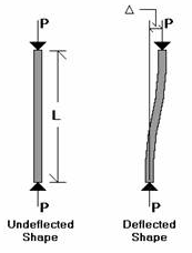
In my mind, if I imagine these columns under full axial load, then the top of the column deflects with the diaphragm under some wind load, how does this not cause a bending moment in the column equal to the axial load times the diaphragm deflection? You mentioned in your post above it only adds more axial load to the column, but I don't understand the statics of where additional axial load (and no moment) comes from. However since both ends of the column are pinned (exception being the top is free to deflect vertically), the moment must only exist along the column length. I am imagining something similar to the pic below:
Capture_n5qal7.png
 
If the column is not part of the lateral resisting system, then the force in the column is still axial, the column is just "leaning" a little. This imparts a little horizontal load into the diaphragm and a little more axial load in the column, as KootK says. The undeflected shape is not an "S", it's still straight, just leaning. (Little P-Delta is a little different, but that's because the column might not be theoretically perfectly straight end-to-end.)

Unless you are evaluating members which are part of the lateral resisting system, the additional force in the column should be very small and you don't need a full-blown DAM run. You just need the buckling characteristics of a section with two different I values.

Is 14' the maximum height you can reinforce the column? For pinned-end buckling, the best bang for your buck is to reinforce the middle section. You might be disappointed in how little your reinforcement helps when compared to the original column weight when you reinforce just the bottom.


Check out Roark's Table 34 Case 1b. It might have just what you are looking for.
 
Given the amount of discussion already occurring on buckling analysis of various forms, would it be possible to post the exact details of loads, lengths, supports, members and reinforcement? It might be a bit much but, you might find people wiling to have run the numbers themselves.
 
human909 said:
Given the amount of discussion already occurring on buckling analysis of various forms, would it be possible to post the exact details of loads, lengths, supports, members and reinforcement? It might be a bit much but, you might find people wiling to have run the numbers themselves.

Sure. The column is W8x40, assumed A36 steel due to early 1990 construction. Bottom of baseplate at (-)12" with a 6" slab at finished floor. Top of column is at (+)29'-3.5". Atop the column cap plate sits a 2.5" joist seat and 6" joist girder seat. Going off of memory here but I think total applied load is ~70 kips due to D+S+RTU load.

Column is reinforced with 10"x0.375" A36 plate from flange tip to flange tip. Plate reinforcement extends from finished floor to (+)14'-0". Plate reinforcement is stitch welded to column w/ 3/16 fillet weld @ 3-12.

The step column approach was perfectly applicable initially. However, at some column locations the client requested to omit the column reinforcement near the bottom of the column in order to leave access to some electrical outlets that were nested into the web of the column. So, I needed to model the plate reinforcement from (+)2'-0" to (+)14'-0" which threw all step column analyses out the window and I've been searching a way to confirm my suspicions that the situation is ok.
 
As BA mentioned, look into Newmark's method. It's curiously and elegantly simple in its application. Most good numerical methods textbooks should cover it. If you can't find anything, let me know. I know I have some hard copy examples buried somewhere I can try to find them tomorrow.
 
lexeng18 said:
I am using RAM Elements which only just recently added the linear buckling analysis feature. To my knowledge there is no capability to capture geometric non linearity effects.

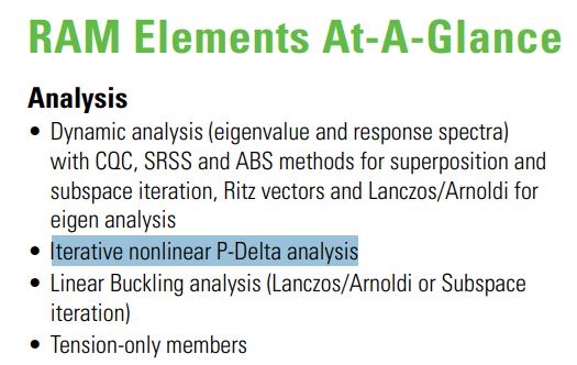
Forgive me for being annoying but I still think that your software likely is capable of doing a geometric, non-linear analysis. I suspect that it's the option that I've highlighted below. Hopefully someone here with more RAM Elements experience can confirm. Alternately, a quick call to tech support or some example testing could confirm this. The stuff below doesn't explicity mention geometrical non-linearity but, given how easy it is to add that in programatically, I'd be astonished if it's not there.

lexeng18 said:
So, I needed to model the plate reinforcement from (+)2'-0" to (+)14'-0" which threw all step column analyses out the window and I've been searching a way to confirm my suspicions that the situation is ok.

Frankly, I'm surprised that the 2' omission at the bottom even makes a difference. Like JLNJ mentioned, it's really the reinforcing in the middle of the column height that should be doing the bulk of the work for your. I'd be interested to be proven wrong but, if it were me, I'd likely not even bother to model the absence of reinforcing in the bottom two feet.

c01_kqrthf.jpg
 
lexeng18 said:
I come from an old school design office where every column in every situation is designed using the effective length method.

1) I came up that way too and, frankly, I think that it represents an opportunity. In my opinion, you and I have have the good fortune to be practicing in what I consider to be the golden age of structural stability. One thing that both the K-factor method and DAM have in common is that both methods reduce to cookbook style methods requiring little in-depth thought. And that's by design as we're all trying to keep errors low and profits high. It's really been in the transition from K-factor to DAM that we've seen a lot of deep thinking engineers question what they thought they knew. Effectively "how dos this new method address these important things that the old method addressed?". In a dystopian future twenty years from now, we may be stuck with a bunch of computer jockies just clicking the "DAM Analays" checkbox and accepting the results blindly.

2) I feel that the K-factor method is actually the most elegant of the methods even if the other methods sometimes are more accurate and more expeditious. To truly understand the development of K-factor, one really has to understand stability because the method reduces a lot of real world complexity down to a relatively simple procedure. As wonderful as DAM is, I really consider it to be something of a brute force computation method.

lexeng18 said:
So maybe I just need to be pointed to a book on the topic but I have never had a solid understanding on the different stability methods that AISC addresses.

3) Over the weekend, I managed to find a pretty good paper for you to address this need: Link. It's fairly concise at 21 pg and was authored by Donald White, one of the notable experts for this kind of thing.

4) When time permits, I'd also recommend a read through AISC's design guide on stability (clip below).

Don't feel that I'm just sloughing you off on these references in place of answering your questions though. I understand that most folks don't have time to do 20 HRS of hard reading just to get some simple answers to some basic questions. By all means, take this opportunity to ask whatever burning questions you may have about the various AISC stability methods. In this thread, you've already got the attention of some folks that excel at this stuff. There'll be no better time than now.

c02_jlllkn.jpg
 
lexeng18 said:
The column is W8x40, assumed A36 steel due to early 1990 construction. Bottom of baseplate at (-)12" with a 6" slab at finished floor. Top of column is at (+)29'-3.5". Atop the column cap plate sits a 2.5" joist seat and 6" joist girder seat. Going off of memory here but I think total applied load is ~70 kips due to D+S+RTU load.

Column is reinforced with 10"x0.375" A36 plate from flange tip to flange tip. Plate reinforcement extends from finished floor to (+)14'-0". Plate reinforcement is stitch welded to column w/ 3/16 fillet weld @ 3-12.

Just to be clear, do you mean one or two plates, 10" x 3/8"? I would have thought two plates from tip to tip of flanges, one plate each side of the web, resulting in a symmetrical section.

BA
 
Status
Not open for further replies.

Part and Inventory Search

Sponsor