Continue to Site

Eng-Tips is the largest engineering community on the Internet

Intelligent Work Forums for Engineering Professionals

  • Congratulations waross on being selected by the Eng-Tips community for having the most helpful posts in the forums last week. Way to Go!

Modelling Band Beams in Ram Concept 2

Status
Not open for further replies.

FreshMan2020

Structural
May 7, 2020
24
Hi all, I have question in regard to modeling band beams in Ram Concept.
Basic Info:
8.5m x 8.5m grid with 2400mm*500mm (D) running in longitude direction.
Band beams are defined as standard beam element with 'meshed as slab' option unticked while slab is defined as one way slab.
Longitude column strip is set to be T-Beam with 'design column strip for column + middle strip resultants' selected. Latitude design strip is set to be one way slab rectangle.


Questions
I want to design slab together with band beams in Ram Concept (strength and service including long term deflection).
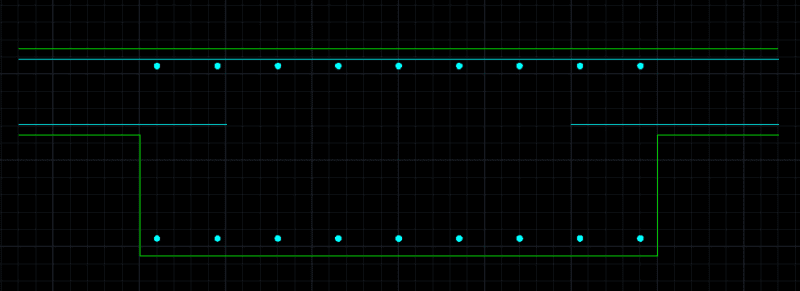
The reinforcement plan in Ram Concept produce 'unwanted' latitude bottom reinforce in band beam area (refer below pic 1). I understand that from analysis results there will be moment in that area in that direction which is why reinforcement is produced. However, I want the band beam to be design as 'one way' without transverse bars detailed as below (pic 2). (no even ligs unless the concrete shear capacity fail). So what do I do in Ram Concept to achieve what I want?

q_gtx1e2.png
pic 1 : Unwanted latitude bottom bar in band beam

1122_tac70t.png
pic 2: actual detail I want to design for slab-to-beam

Thank you.
 
Replies continue below

Recommended for you

Below is the layout plan.
m_fxm31j.png


I have also circled the 'unwanted' latitude bottom bar in band beam as below
q_-_Copy_a3qa17.png
 
I have no ideas or experience about how to use that software. My first suggestion would be to consult your mentor, then to consult the software manufacturer's rep. What is shown on the plan you included is obviously nonsensical. But are you relying on software to make your reinforcement selections? The first thing which struck me is that all the bars are N12, which means a lot of bars.
 
Hi hokie66, this is in regard to Ram Concept but I think it applies to other FEA packages. I am not sure which part is nonsensical to you, can I kindly ask you to elaborate? I am not relying on the software to make reinforcement sections. What I want to do here is I want to design it in a traditional way: band beam supporting one way slab without any bottom transverse bars in band beams. However as I assign the slab as a whole there will be bending moment across band beam which will force the Ram Concept to place bottom transverse bars across the band beams so I am wondering what changes (if possible) can I make in Ram Concept before analysis and design. I am using it to check the long term deflection which can not be done by hand (at least not when the structure becomes more complex) and the way I design it (not limit to these transverse bars) will affect the results I think?

These is not a concern for me, I can replace with N16 or whatever.

Thank you.
 
There is bending moment across the band beam, but in the bottom, it is in compression. No reinforcement required, except some support bars to keep all your longitudinal bars in position. But I should defer to others, as I have never used a finite element package in the design of concrete slabs.
 
Yeah. You are right. Forgive my stupidity on this. Wonder why Ram Concept still produce bottom bars in these areas then. I do think of one scenario when there are way stronger supports paralleling to band beams on both sides of them then there might be some positive moment across band beams but this is not the case here/.
 
Those bars are being added to fulfill minimum steel requirements for the larger cross sectional area of the beam. Increase the support width for the one-way slab strips so the first and last design sections occur at the faces of the band beams. Also make sure torsion for the design strips is not set to "none" unless you have defined both the slab and beams to be "no torsion", there is a chapter in the manual on the available options.

Alternatively you can change the strip options for minimum steel, see the manual for the options.

For a layout like this I'd also add to investigate patterned live loads.

To verify why those bars are there go to the bottom reinforcement design status plan and in the options, eye ball button, check the box for controlling criteria, the governing code section will be added to the bar tag.

My Personal Open Source Structural Applications:

Open Source Structural GitHub Group:
 
Have not looked at RAMConcept in a long time, but I would think defining the band as a "Beam" would mean that it does not consider the transverse bending over the band beam width associated with slab bending. Normally a "beam" in FEM is modelled as a longitudinal 2D element, not a plate or slab 3D element.

A Band beam is really a thickened slab and the beam area needs to deflect transverse to the beam direction and the band area is defined as a thickened slab area.

Many designers refuse to use FEM design programs for band beams, instead breaking it down to runs in both directions.
 
Rapt can you elaborate the last part please
 
I don't get the logic here. The band beam is defined as 'beam' and I don't think there is such a minimum transverse steel requirement for beams?

I will go through the manual in details later. Thanks
 
This is what I thought. There is a 'mesh as slab' option when defining as beam but I didn't tick. I would expect the beam in that area has higher priority than slab when it comes to design and the minimum steel requirement as Celt83 mentioned for slab will be overwritten.
 
Defined as a beam or not doesn't matter for the slab strip. Assuming your slab design strips are the latitude strips, if you go into the strip properties I'm guessing they are setup with the design system as one-way slab and not beam. If you have not defined the support width to be equal to or wider than the "beam" then you are getting a design section inside the beam perimeter which has the depth of the beam, increasing the cross sectional area thus increasing the minimum steel requirement. The default behavior for slabs is to place minimum steel on the bottom face and the strips in this direction are set to follow the slab design rules.

You are seeing multiple sets of short bottom bars because of the cross section trimming, where the program gradual steps the effective section depth along areas of soffit changes in successive design segments.

Audit the cross section and step thru the report it goes thru the programs design process and gives you the cross section dimensions being used for design.


My Personal Open Source Structural Applications:

Open Source Structural GitHub Group:
 
In my opinion, a tool like RAM Concept is a bit overkill for a problem like this.

I would use a 1D software, such as RAPT. One design run/direction being a typical band beam and one being the slab in the transverse direction.


The short bars in the beam strip looks like shear reinforcement (complete hoop in the middle beam, and sideway U for the edge beam), but I don't know why the program provide such bars in E-W one-way slab design, and why it indicates all such bars as bottom bars.
 
efr

Trenno basically explained it, except I think 1D is a bit tough!

In RAM you are doing a 3D analysis and trying to use that to do a 2D design, ignoring a lot of what the 3D analysis has done. If you want to design it as a beam and Slab design, then you should analyse it that way, and save yourself a lot of time on the way.
 
Sorry RAPT, was thinking in FEA language - i.e. frames = 1D, plates = 2D and bricks = 3D.


While a tool like Concept might be overkill for something like this if it's the only tool you have available or that your company found financially viable to purchase then you need to learn how to use it properly. I strongly recommend you read the manual.

My Personal Open Source Structural Applications:

Open Source Structural GitHub Group:
 
Okay. Now this make sense to me. Just expected the latitude design strip would recognize where beam is and not apply the design rule for slab in that area. Thanks you very much.
 
I agree. But it is also a good way to start using FEA packages from smaller and simply projects IMO.
 
Try and match the results (moments, shears, deflections) from your frame based software and RAM Concept.

Deflections are the trickiest, many factors go into long term concrete deflection.

I usually use a combination of RAPT and RAM Concept. If the results are within cooee, I can trust the design is reasonable.

 
Status
Not open for further replies.

Part and Inventory Search

Sponsor