Continue to Site

Eng-Tips is the largest engineering community on the Internet

Intelligent Work Forums for Engineering Professionals

  • Congratulations KootK on being selected by the Eng-Tips community for having the most helpful posts in the forums last week. Way to Go!

Moment Connection when Minor axis bending is large 8

Status
Not open for further replies.

NewbieInSE

Structural
Dec 19, 2019
234
Dear Engineers,

I have got a Beam Splice to design, which has both major and minor Bending Moment (BM). Major BM is 138 kN-m (102 kip-ft), Minor is 30kN-m (22 kip-ft). Please see the snapshot below.
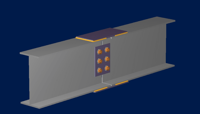
image_odav4l.png


It is taken from RAM Connection Program. The minor BM has been included in the program, but it used only the Major BM.
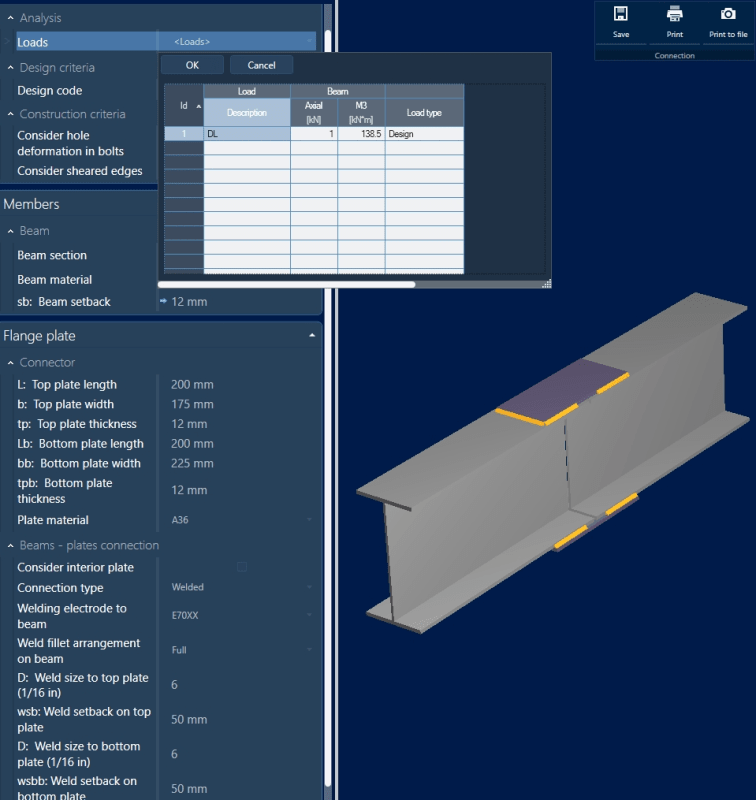
image_qixtqb.png


What I want to know is, the weld shown here for Major BM design, will it be adequate for Minor BM too? or Does it require further checks?

Thanks.
 
Replies continue below

Recommended for you

The plate takes the compression solely after the weld to the next weld for the weak axis moment, as such extra checks are advised not only on weld length but distance required.

"Programming today is a race between software engineers striving to build bigger and better idiot-proof programs, and the Universe trying to produce bigger and better idiots. So far, the Universe is winning."
 
rowingengineer,
I did not understand what you meant by this.
The plate takes the compression solely after the weld to the next weld for the weak axis moment
 
Yes, I would check the connection plates, and weld, for minor axis bending.
 
If major and minor bending moments are concurrent, you can calculate an statically equivalent flange force to design the flange plate and weld. It can be calculated as:

Puf = Pu/2 + (Mux/(d + tp)) + 4Muy/bp

Where:
Pu = Beam axial load (if any)
Mux = Major bending moment
Muy = Minor bending moment
tp = Flange plate thickness
bp = Lesser flange plate width

I think this is a reasonable conservative approach, especially for the design of the weld.

If you want to design the splice using RAM Connection, then you must apply the major bending moment (Mux) in combination with an equivalent axial load equal to: Pue = Pu + 2*(4Muy/bp)

Hope this help!


We are not told the size of the beam. I assume that the flange width is 8" so that field welds will all be downhand. The weld to the top plate is along each side and each end, shown by the thick yellow line. The weld to the bottom plate is along each side, but if the weld is to be downhand, presumably not on each end.
Edit: Sorry, I used the wrong moment. Ignore blue highlighted text. See red text below.
[highlight blue]For a minor axis moment of 138 kN-m and a width of 200mm, assuming only the side welds to be effective, the force transferred between beams is 138/0.2 = 690 kN, half top and half bottom. The weld length per beam is 100mm, so the force per mm of weld is 690/(2*100) = 3.45 kN/mm for minor axis bending alone. This will add to the major axis bending moment weld on one side and subtract on the other.[/highlight]

For a minor axis moment of 30 kN-m and a width of 200mm, assuming only the side welds to be effective, the force transferred between beams is 30/0.2 = 150 kN, half top and half bottom. The weld length per beam is 100mm, so the force per mm of weld is 150/(2*100) = 0.75 kN/mm for minor axis bending alone. This will add to the major axis bending moment weld on one side and subtract on the other.

I don't understand the computer output where it says "Weld size to bottom plate (1/16 in)", then shows an entry of 6 with no units in the column to the right. All other dimensions in that column are in mm, so I assume the default weld size is intended to be 6mm, substantially more than 1/16". Doesn't look like the specified weld is adequate for minor axis bending, let alone major axis bending.

I don't know why a WF beam is being used with such high minor axis moment. I don't like it, but perhaps there is a valid reason. I would certainly question the weld churned out by the computer. I still don't like it, but it's not as bad as I first thought.

BA
 
I usually take pause whenever the program doesn't allow input of a certain force, because often the developers have spent 100's of hours developing the program for each connection and have some valid research to back up their decision to exclude the allowance, but sometimes it seems that they just run out of time, or get lazy, and don't add certain functions. I just checked RISA connection and it doesn't include weak axis moment checks on this connection either.

I've never seen this detail used for significant weak axis moment, but like others have said the weak axis moment should be converted into a triangular force distribution on the flange plates, max compression on one side, max tension on the other. Additional design checks are basically just checks for the weld and weld base metal, with tension/compression from weak axis moment added to tension/compression from strong axis moment. (maybe flange plate buckling, but I doubt it with that short of an unsupported length).
 
BA,

The minor axis bending is 30 kN-m (22 kips-ft), but can be concurrent with the major axis bending, which is 138 kN-m (102 kips-ft), as noted by PROYECTOR.
 
retired13,

Yes, thanks. I have edited my previous comment.

BA
 
Thanks Proyector, Could you give me a reference on that formula to check out in depth?

BAretired, Thanks for your analysis. Flange size is as you guessed. Weld size is actually 6 of 1/16 inch = 6/16*25.4mm = 9.5mm. The plate lengths are actually 200mm in each side of the separation point. so the force per mm weld is 150/2(200-2*25)=0.5kN/mm. 25mm is the setback from the separation point to the start of weld. Anyway, I am not much good at undrstanding weld strength. I need to go books.

MegaStructures, Yeah, it is very disappointing. At the time input, program takes all inputs, but when utilizing the data, its not considering one or two data, which someone might think the program to have taken into consideration, but may result in bad situation.

Thanks all, give me some sources of small readings in this regard, so that I can do it manually.
 
@All
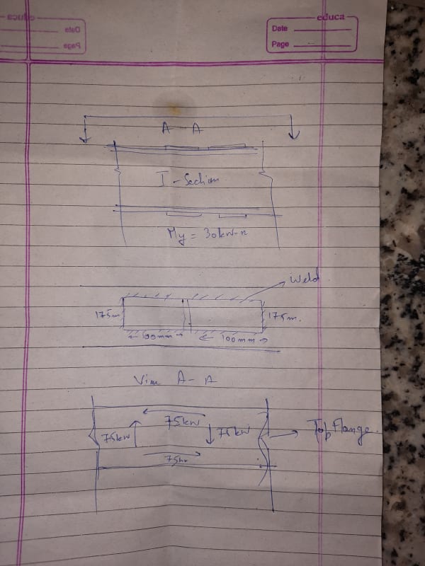
As the minor axis momemt is 30kn-m .It will be divided between the top and bottom flange i.e each flange will resist 15kN-m of load. Thus the force in the flange will be 15/0.2 = 75kN.
Thus force in weld along lengtb 75/200=0.375kN/m
Also i will result in formation of couple like shear .Thus force in weld along width =75/175= 0.428kN/m
Is my understanding correct?

20200830_143646_qrqtap.jpg
 
@BARetired As u said it will be added on one side amd subtracted on the other.My understanding is if my top flange in in compression amd due to minor axis moment my one side of flange is in compression and other in tension thus for one side we will be subtracting and for other we will be adding.Is my understanding correct?
 
Sammy,

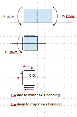
FYI on weld design (for M[sub]y[/sub] only. Note that minor axis shear, V[sub]y[/sub], needs to be added, if present). You shall also check the strength of the connection plate for the minor axis bending and shear.

image_qda4ya.png
 
@retired13 So is my understanding correct.Our drawings are matching.
But I have one doubt.When calculating the force for the weld we are adding the major axis bending momemt force to get the critical force for weld.
In case of simple I Builtup beam we design tge weld between web amd flange for only shear force that is acting on the beam and we never consider tge major axis bending moment force for weld calculation.
Why?
 
The web connections needs to be designed for the moment caused by eccentricity of shear (likely not present here), but the major axis bending is assumed to be taken up by the stiffer flange connection. Always think about which part is stiffer and will carry the load first.

I'm confused is Sammy345 and OP the same person on different accounts?
 
@Megastructures I just saw the post and wanted to know the concept.I am only handling this account.The OP is some other person
 
Got you. I thought Maybe Kevin Durant took up engineering.

To expound on my stiffness comment. As the member rotates the flange connection, farther away from the N.A., will take up force and stop the beam from continuing to rotate. At this point the web connection will have rotated far less, again due to it's relative location to the N.A., and will not develop significant stress from the rotation.
 
@ Megastructure I am talking about forces on weld and you are talking about stiffness.
 
Sammy,

In this case, the minor axis bending becomes torsion on the half connection plate, so it is additive to the stress due to major axis bending (Fw = Mx/d), as both resulting in shear in the weld. Note that the shears are to be added together as vectors if they orientate in different direction/axis. Also, do not substract shears in opposite direction, but to use a single weld size for the largest force in the weld lines.

When design the flange to web connection in a built-up section, we consider shear (V) only, because moment is the integration of shear force, that is the source of deflection and curvature, for which the flange and the web have to be built in accordance to the rules of compatibility and stress equilibrium. I hope this helps. But I think BA/KootK maybe able to provide a better/clearer explanation.
 
Status
Not open for further replies.

Part and Inventory Search

Sponsor