Continue to Site

Eng-Tips is the largest engineering community on the Internet

Intelligent Work Forums for Engineering Professionals

  • Congratulations KootK on being selected by the Eng-Tips community for having the most helpful posts in the forums last week. Way to Go!

Moment Connection when Minor axis bending is large 8

Status
Not open for further replies.

NewbieInSE

Structural
Dec 19, 2019
234
Dear Engineers,

I have got a Beam Splice to design, which has both major and minor Bending Moment (BM). Major BM is 138 kN-m (102 kip-ft), Minor is 30kN-m (22 kip-ft). Please see the snapshot below.
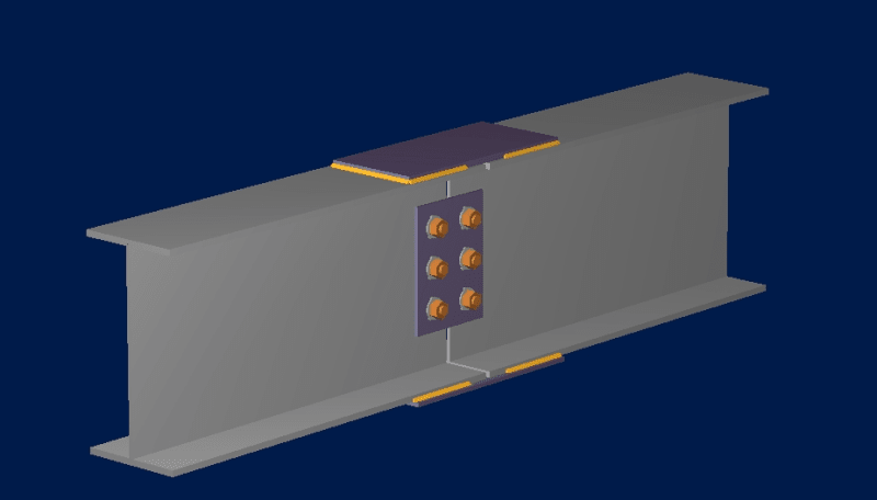
image_odav4l.png


It is taken from RAM Connection Program. The minor BM has been included in the program, but it used only the Major BM.
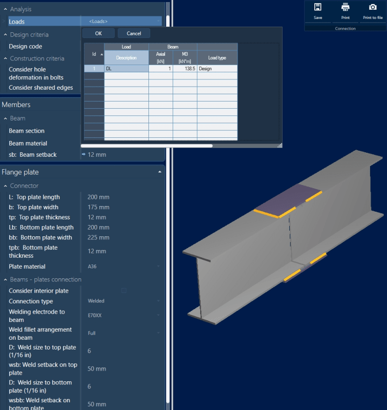
image_qixtqb.png


What I want to know is, the weld shown here for Major BM design, will it be adequate for Minor BM too? or Does it require further checks?

Thanks.
 
Replies continue below

Recommended for you

@BARetired Firstly this 30kN-m is applied to the whole beam cross section.Thus Top flange will take its share of 15kN-m and bottom flange will also take care of its 15kN-m.
For tge purpose of understanding let 30kN-m be applied to top flange only. Then Why are you dividng the force to side weld? Like you said 150kN or 75kN each side weld.(My= 150x0.2=30kN-m ; 75x0.2=15kn-m).The first one in bracket is correct as we get the same applied minor moment while the other one is incorrect).So it should be 150 kN only to each side weld and not 75kN.Am I missing something?
I did my earlier calculations considering only 15kN-m to top flange only.
Also why couple like shear would not be generated .The forces are actimg on the flange on opposite direction due to minor axis momemt.Suppose in clockwise direction .To maintain equilibrium tghe other two forces must be genrerated in anticlockwise direction like it happens in shear. Can you please expain?
And why are u adding major axis moment to weld design ?
We don't do it when we are designing weld betwwen web and flange of Builtup I section .Why are we doing it here?
 
dik said:
Am I the only one that uses tb^2/4 for plates?

That is the plastic section modulus, dik. You are not the only one to use it. I would use that for strength calculations if that was the only moment acting on the plate, but if we want to know the maximum stress in the plate as a result of M[sub]y[/sub] on the beam, we must use elastic section modulus. The minor moment M[sub]y[/sub] can't engage the plastic section because the plate will be stressed simultaneously by the major moment M[sub]x[/sub].

BA
 
Sammy345 said:
For tge purpose of understanding let 30kN-m be applied to top flange only. Then Why are you dividng the force to side weld? Like you said 150kN or 75kN each side weld.(My= 150x0.2=30kN-m ; 75x0.2=15kn-m).The first one in bracket is correct as we get the same applied minor moment while the other one is incorrect).So it should be 150 kN only to each side weld and not 75kN.Am I missing something?
I did my earlier calculations considering only 15kN-m to top flange only.

You were correct to use 15kN-m for the top flange only. The bottom plate takes the other 15 kN-m. That means the weld on each side of each plate takes 15/0.2 = 75kN as a result of M[sub]y[/sub].

Sammy345 said:
Also why couple like shear would not be generated .The forces are actimg on the flange on opposite direction due to minor axis momemt.Suppose in clockwise direction .To maintain equilibrium tghe other two forces must be genrerated in anticlockwise direction like it happens in shear. Can you please expain?

The couple like shear is not generated unless the plate is also welded to the ends of the top flange of each beam. It is true that an end weld would contribute slightly to resisting M[sub]y[/sub] but not as a couple the way you envisioned. The couple would need to be applied to both beams. Furthermore, welding across the beam flange is considered bad practice because it weakens the beam. It can't be done on the bottom plate without overhead welding, so I considered only side weld and no end weld for both plates.

Sammy345 said:
And why are u adding major axis moment to weld design ?
We don't do it when we are designing weld betwwen web and flange of Builtup I section .Why are we doing it here?

Yes we do do it between web and flange, but we have half the length of the beam in which to do it. When you calculate the shear flow in the weld, you use the expression VQ/I. and if you add that up between support and maximum moment, you will find that it is identical to the flange force at maximum moment. In this case, however, the flanges of both beams terminate at the splice. The splice plates have to carry the entire major moment M[sub]x[/sub] with a lap of only 200mm on each beam. To get the force into the plates, you need plenty of weld in that short length.

BA
 
retired13,

You are talking about a transverse weld. I believe it is considered bad practice to weld across a flange as it weakens the beam. It can't be used on the bottom flange without uphand welding, so I used only side welds to carry both major and minor moments. That makes welding for both plates similar.

BA
 
I would instead use the term 'moment in the plane of the weld group' instead of 'torsion' in Retired13's sense. And polar moment of inertia of the weld group instead of Jw. The numbers are the same though.

BAretired, how serious is welding across the flange? What about stiffeners which have two cross-flange welds at close spacing?

Dik, I don't treat longitudinal and transverse welds as having different strength.
 
Technical terms often are exchangeable, important are the method and results. The difference been, when conservation brings up bending moment and stress, we are likely immediately linking it to the normal stress, f = M*y/I; on the other hand, when we see a calculation expresses stress as, f = M*r/Ip, we will link it to torsion, even though the presence of moment abbreviation.
 
Comparing to BAretired's numbers from 30 Aug 18:02: BA gets 213kN/200mm = 1.065kN/mm weld stress. This is an assumed uniform longitudinal stress

Retired13's elastic analysis gives 1.011kN/mm peak stress at two points (either end of the 'additive' weld). The direction is a little oblique to the weld direction. This is based on the same two parallel welds as BA's analysis. I expected this method to give a higher stress tbh. I think what I overlooked is that the lever arm for minor axis bending resistance is bigger for the elastic case which overcomes BA's averaging along the weld length. The averaging effect is smallish for this geometry and then reduced further because the major axis stress dominates and the peak minor axis stress is at 45 degrees.
 
Dear all,
Forgive my silence being OP. I don't understand a lot of things you are talking about which I need to learn to talk about.
Anyway, you may continue the discussion since it may be of benefit to me or someone else.
 
Newbie,

I suggest to open up an engineering mechanics textbook to review the equations for shear stress, normal stress (tension/compression), torsional stress and shear flow, then you know what has been discussed here.
 
I understand those stresses. Maybe I need to check out some weld design examples.
 

Might be missing something here... doesn't it just change the size of the rectangular stress blocks so that resultant is equal to the Tf and Mf? The reduced plate still has its tensile and flexural capacity.

Dik
 
You can download the "Design of Welded Structures", by Omer Blodgett, on the linked site. When prompted to "upgrade", don't, select the tap says "this paper only" instead. It is free. Link
 

I don't either usually, a matter of convenience, only. I don't know if I'm losing some significant value by ignoring them.

Dik
 
dik,

I think most people, me included, ignores the additional strength provided until desperate needs.
 
I think most people, me included, ignores the additional strength provided until desperate needs.

The plate is automatically about 50% thicker... big change.

Dik
 
steveh49 said:
I would instead use the term 'moment in the plane of the weld group' instead of 'torsion' in Retired13's sense. And polar moment of inertia of the weld group instead of Jw. The numbers are the same though.

BAretired, how serious is welding across the flange? What about stiffeners which have two cross-flange welds at close spacing?

I think it is a precaution for field welding in situations where the structure may be compromised by weakening part of it by welding. Although not specifically stated, these welds are clearly field welds as evidenced by bolts in the web. We do not know where in the structure this splice occurs, so it may not be serious at all. It seems like a daft sort of splice to me, but who knows, maybe there is a good reason for it.

The second reason for avoiding transverse field welds is the overhead welding which would be required on the bottom plate. It would be more economical to make the plates a little longer and put the weld on the side.

However, if we are determined to weld across the flange, I would not consider that weld as contributing to M[sub]y[/sub] where it is only marginally useful. Instead, I would deem it to be resisting M[sub]x[/sub] where it is 100% useful.

You are correct about the weld group, steve. If there is to be a 'U' shaped weld on each beam, the stress will be sort of a torsion on the weld group. There is no torsion on the plate, which is what I first thought retired13 was claiming.

BA
 
You are correct about the weld group, steve. If there is to be a 'U' shaped weld on each beam, the stress will be sort of a torsion on the weld group.

Thanks BA for clear me up :)
 
NewbieInSE said:
Thanks Proyector, Could you give me a reference on that formula to check out in depth?

There is no reference, just statics assuming a plastic stress distribution in the flange plate due to minor axis bending. However, there is a quite similar approach for bolted column splices in Tamboli's book "Hand Book of Structural Steel Connection Design and Details".

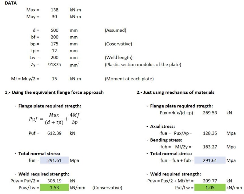
The equivalent flange force approach is just a design simplification that may be quite conservative for the weld design (it works better for bolted splices).

For the weld design, I would ignore the transverse weld segment as suggested by BAretired. You could design each C-shaped weld group using the instantaneous center of rotation or any other method, but since you only have C-shaped welds at the top flange, it's not really worth it.

I find the following quote very relevant to this discussion:

Bo Dowswell said:
A good design model is one that produces sufficiently accurate results in a reasonable amount of design time. In many cases, connection design time can be greatly reduced if the designer recognizes that the calculations are not always required to be theoretically correct. Over-complicated, theoretically correct design models can cost more money in engineering time than they may save in fabrication and erection costs. When more than one design model is available, the connection designer must decide which one to use.

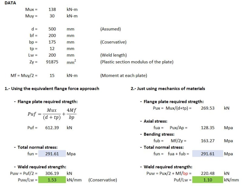
Attached is a comparison between the equivalent flange force approach and a more theoretically correct design model. The plate acting stresses are calculated for comparison purposes only.

Calculation_example_bu5tfd.jpg
 
Sorry, there is a little errata in the above calculations. The modification is indicated in red...

Calculation_example-2_fdnn8e.jpg
 
retired said:
You can download the "Design of Welded Structures", by Omer Blodgett, on the linked site. When prompted to "upgrade", don't, select the tap says "this paper only" instead. It is free. Link

This is by far one of the best structural steel design books ever published, thanks for sharing!


Status
Not open for further replies.

Part and Inventory Search

Sponsor