Continue to Site

Eng-Tips is the largest engineering community on the Internet

Intelligent Work Forums for Engineering Professionals

  • Congratulations cowski on being selected by the Eng-Tips community for having the most helpful posts in the forums last week. Way to Go!

Moment resistance of a concrete beam with two different f'c 2

Status
Not open for further replies.

skewl

Structural
Jul 27, 2021
46
Based on the Canadian codes (A23.3 / S6), moment resistance of a concrete beam can be found by determining "c", finding the equivalent rectangular stress block, and obtaining the compression forces in the concrete. This is all fine for a rectangular beam with the same concrete material. However, what do you do in situations where the concrete beam has two different compressive strengths?

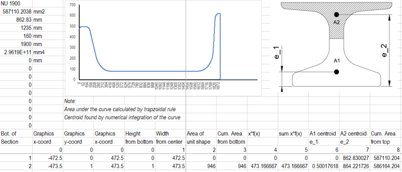
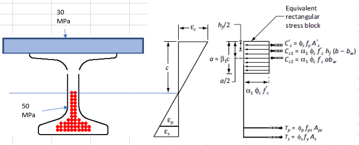
For example, I have a 50MPa pretensioned NU girder acting compositely with a 30MPa deck slab. The N.A. of the composite section ("c") is within the web on the girder so both types of concrete are engaged. In this case:
1) How do you determine "a" (i.e. a = beta*c)? The alpha and beta factor is dependent on the material properties of the concrete (i.e. beta = 0.97-0.0025*f'c).
2) My understanding of the beta factor is that it converts the "non-uniform stress block" acting on a rectangular section to an "equivalent rectangular stress block" acting on a rectangular section. The NU girder is not a rectangular section and its width varies non-linearly with depth. Is it still correct to apply the beta factor to "c" to find "a" in this case?
3) My current approach is to transform the width of the deck slab by n = Ec,g / Ec,s (like what you would do in a steel-concrete composite beam), and then assuming f'c = 50MPa in all my calculations.

Capture_q2b8ve.png


Unfortunately my company doesn't have software to do pretensioned beam design so I am unable to verify my calculations with a computer program. Any advice/literature on this is appreciated.
 
Replies continue below

Recommended for you

You describe two issues. First, the shape of the compressed section is non-rectangular. Second, you inquire how to account for two different concrete classes.
Let me start off by answering your questions briefly:
#1 For one concrete class (and up to a certain strength level), this is received by applying the Whitney-method (equivalent rectangular stress block). In your case, with two different concrete classes, numerical integration will be needed.
#2 No, it is not correct, since the equivalent stress block method assumes a constant width, i.e. a rectangular section.
#3 Numerically integrating the stress from "strain_0 = e_cmin = 0" to "strain_max = 0.35% = e_cu" will render such tricks unneccessary.

Have a look at Eurocode 2, equation 3.1.7 (1) and 3.1.7 (2). Therein, a description of the concrete compressive stress as a function of strain is given. Using this compressive stress block, you can find the resultant concrete compressive force by numerically integrating (e.g., in Excel, using the trapezoidal formula) the stress, multiplied by width, multiplied by the differential. Formally:

F_comp_resultant = integral (sigma(y)*b(y)*dx)

, where dx = step-size , b(y) = width as a function of height (this can be given as discrete values in your excel table), sigma(y) = stress, and y = vertical location in the cross-section (above the neutral axis, of course). For the step-size, you can use e.g., 40 points, defined using the distance from N.A. to the upper fiber: "dx = (upper_fiber - N_A) / 40 ".

To find the resultant of the concrete compressive block, re-do the previous calculation, but now add a lever arm to the centroid (measured from the N.A.) of each "small increment of force" and subtract this result from the distance to the N.A. (in your notation, that is "c"):

a = c - integral (sigma(y)*b(y)*y*dx)

To find the internal lever arm (where d = effective depth), calculate:
z = d - a

Googling "numerical integration of concrete compressive block", or something to that tune, may help in clarifying what I attempted to describe.

Your bridge girder and deck form a "T-beam", and since you said that the N.A. is in the girder web, you need to use superposition to acquire correct results. Simply integrating the whole section is not possible, because there is a discontinuity in stress-strain at the deck slab/girder interface.

First calculate the moment capacity (force resultant, its location and the lever arm) for the girder (everything below the deck slab). Then, calculate the moment capacity for the deck above the girder. Then, calculate the moment capacity for the part of the deck located to the right and left of the girder ("outstand flanges" so to speak). To account for different concrete strengths, use "fc = 30 MPa" for the girder web calculations and "fc = 50MPa" for the deck calculations.

PS. It may be wise to consult a local senior engineer for this task, since it is not a "run-of-the-mill" design.
 
If it passes under the assumption that the concrete is all 30 MPa using the rectangular stress block parameters, you can avoid the detailed calculation.
 
Thank you centondollar, what you described makes sense, especially the portion regarding the strain compatibility method.

After I posted, I did find some information from a prestressed concrete design example from FHWA regarding the different concrete strengths. However, your method seems to be the correct way of looking at this problem.

Capture_y5xpiq.png
 
The picture you posted details the T-beam design concept, and the modular ratio-approach (culminating in transforming girder flange/deck slab into a homogeneous section) does seem to be one way to account for the varying concrete strength. I recommend to verify this by further research and/or by asking a senior engineer for advice. Also, please note that the T-beam discussed in that document appears to be rectangular (rectangular web, rectangular flange and rectangular deck slab), and the equations may therefore not be directly applicable for your design.

The method I described is the most general approach to determining the compressive block resultant force, its location and the internal lever arm. A bi-linear concrete stress-strain diagram may also be used, and in some literature, a rectangular stress block with empirical multipliers is used. As a final note, I would recommend to use the semi-parabolic concrete stress-strain diagram (found in EC2 1992-1-1 and probably also in ACI) and numerical integration to determine the concrete force resultant, lever arm and moment capacity.

PS. You can easily find the width as a function of height (b(y)) by using AutoCAD or other drafting software. Determine the neutral axis, discretize the compressive block (e.g., into 40 "slices"), measure the average width of each "slice" and input these values into Excel or similar software. Furthermore, locating the force resultant does not necessarily require numerical integration if you integrate from "e_c = 0%" to "e_cu=0.35%", since it results in compressive blocks with known centroids (semi-parabola and rectangle or triangle and rectangle, depending on the stress-strain material law you choose to use) which you can then utilize, e.g., "M_capacity_total = (d-centroid_semiparabola)*force_semiparabola + (d-centroid_rectangle)*force_rectangle", where the centroid distance is measured from the extreme compressive fiber and "d" is the effective depth.
 
After checking out EC2 1992-1-1, I do agree with your approach and will start working on integrating that into my spreadsheet. Fortunately, my spreadsheet was already doing numerical integration for areas and centroids so adding in the stress calculation at each slice shouldn't be a big modification. My senior engineer is always busy but I definitely should go talk to him [bigsmile]. Thank you again for your help!

Capture_jpex41.png
 
Status
Not open for further replies.

Part and Inventory Search

Sponsor