Continue to Site

Eng-Tips is the largest engineering community on the Internet

Intelligent Work Forums for Engineering Professionals

  • Congratulations KootK on being selected by the Eng-Tips community for having the most helpful posts in the forums last week. Way to Go!

Motor Shaft Failure

Status
Not open for further replies.

Aptx4869

Mechanical
Mar 1, 2018
44
Hi All

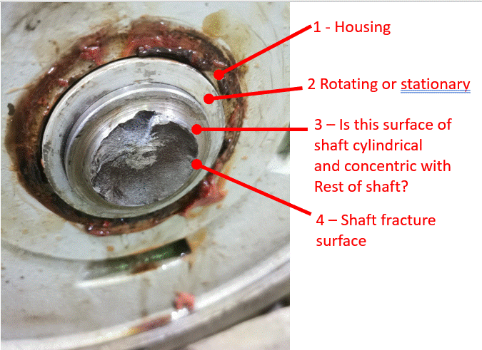
Recently we had a failure on a motor shaft (attached)

the motor is vertical and connected to lube oil centrifugal pump via grid coupling

After the failure, we confirmed both motor shaft and pump shaft are rotating freely

The only finding was pump shaft runout to be 7 mils. We measured that runout with pump assembled (not on V block)

New pumps will have 2 mils or less when we measure the shaft runout with pump assembled.

Any idea if that amount of runout will cause such failure ?


 https://files.engineering.com/getfile.aspx?folder=fb3a6ac5-f281-4c04-967a-5944527457c8&file=IMG_20220511_131320_resized_20220515_061216399.jpg
Replies continue below

Recommended for you

Unknown shaft and coupling size, but grid couplings require good parallel alignment. It looks like a heavy bending load was induced due to .007" misalignment.
 
The data sheet for the coupling should give you the bending stiffnesses for the coupling. That info and the .007 runout would allow you to figure out the load on the motor shaft from the misalignment.
 
Hi dvd

The coupling size is 1060T and shaft size is 1 1/8"

Just to clear one thing, What I mean by runout is shaft deflection where the dial base is fixed on pump housing or support and the dial pin is on the shaft. rotate by hand and see how much high spot is there.

I know it is not common to measure shaft deflection with pump assembled, since the v block method is the one usually mentioned in manuals
 
For alignments readings, we couldn't take the as found reading since the shaft was already broken


Are you measuring the runout with the coupling installed and all bolts tight? That's not the way to do it because the coupling stiffness will possibly reduce the apparent TIR on one of the shafts.
 
Hi BrianE22

No. Of course with coupling de attached.

Also with coupling hub removed, so we can put the dial directly onto the shaft and see if there is any deflection

We got a value of 7 mils on pump shaft as mentioned in the original post
 
One thing I forgot to mention, if we measure the runout with coupling hub installed on pump shaft (coupling de attached from motor), we get 12 mils which tells there was some coupling eccentricity

If we measure directly on the shaft (with coupling hub removed) we get 7 mils
 
Please post pictures showing the pump and motor installation. general arrangement.

Maybe it is the camera angle, but it looks to me like the coupling hub is not seated very far onto the motor shaft. The potential for extra bending force due to overhang needs to be evaluated.

What is the repair history of the motor? The shaft shoulder and radius look kind of raggedy, like weld repairs were made in that area followed by finishing by turning n a lathe with less than optimum tooling.

What was the condition of the grid ? Dry, or greasy?
Pictures of the grid and hub tooth wear are always helpful.

.007" TIR is only .0035" offset of the pump centerline. I'm guessing if the grid is in decent condition and well lubricated it would handle that offset without causing much radial force.
 
Thanks Tmoose

Please see the how the hub is fitted in the shaft and condition of the teeth. teethes have wear on them (attached)

I am not sure about the grid condition , but what I remember it was replaced and greased few months before the failure.

For the TIR, when we measure with coupling hub installed we get 12 mils, and 7 mils without coupling hub

The pump has a mounting which I if I am not mistaken called register fit (attached also) and as per manual this mounting is fixed by a rabbet fit to ensure alignment.

Let me check for the shaft history.


I can't figure out exactly what I'm looking at in the 1st photo.

What is piece 2? For starters, is piece 2 rotating or stationary? It's painted as if it's stationary. But the larger gap around the outside of it with grease coming out looks like the clearance between rotating shaft and stationary parts which would suggest piece 2 is rotating. If piece 2 is an inner ring, then it's so far out of the stationary hole that I'd think the cage/rolling elements would be contacting the stationary housing. If piece 2 is a part of the shaft then it's partially painted with a clean line between painted/unpainted and there would be two shaft steps very close together (I'm not saying that's a problem, just trying to figure out what I'm looking at).

Also looking at arrow 3 pointing to a portion of the shaft... is that portion cyclindrical and concentric with the rest of the shaft? It looks tilted to me (maybe that's just the angle).

question_p50bdo.gif


=====================================
(2B)+(2B)' ?
 
electricpete

Piece 2 is rotating and functions like slingers

Point 3 being concetric or not, I will take a look at it again maybe tomorrow, since these are the only photos I have currently.
 
ok thanks, now piece 2 makes more sense.

As far as whether that surface 3 is cylindrical/concentric, from that view it almost looks like you have a conical section of shaft which blends smoothly into the radius of the shaft step, but surely that's just a trick of the camera angle.

I don't really recognize any "classical" obvious failure mode in the shaft fractures, like for example shown here. Often for fatigue failure you can see obvious beach marks in photos like yours, but sometimes it needs closer inspection or maybe just more expert eyes than mine.


=====================================
(2B)+(2B)' ?
 
Status
Not open for further replies.

Part and Inventory Search

Sponsor