Eng-Tips is the largest engineering community on the Internet

Intelligent Work Forums for Engineering Professionals

  • Congratulations waross on being selected by the Eng-Tips community for having the most helpful posts in the forums last week. Way to Go!

Need guide / suggestion on lateral design

Status
Not open for further replies.

ETET001

Structural
Aug 2, 2018
14
AU
122_l3h9bk.jpg

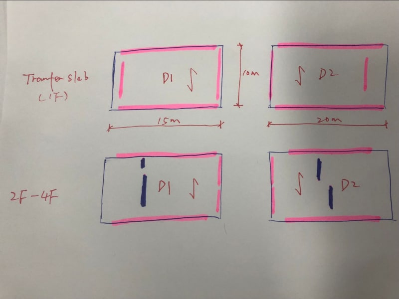
Hi all, I am designing a multi-storey buidling which has a transfer slab on the frist floor. Because of this transfer slab, the walls above 1F cannot work as shear wall as they dont go all the way to the ground.(Please correct me if I am wrong). So the only walls I can rely on are the core walls. But the thing is the as there are two stair/lift voids in the middle. I have to design them as two diaphrams and as a result, I dont think they can work as core walls (Please correct me if I am wrong), which means the stiffness will be not enough. Any input for the lateral design please? Thanks
 
Replies continue below

Recommended for you

You can design the transfer slab to transfer the lateral shear to the outside walls at the main floor. You're actually in a fairly good position from a geometry standpoint.
 

Thanks jayrod12. Are you saying that the non-core walls can still work as shear walls for second floor and above even though they stop at transfer slab on the first floor?
 
Correct. But your transfer slab must be stiff enough to transfer those walls to the main floor walls.
 
Jayrod is correct. Note that ASCE 7 refers to this as an out-of-plane offset irregularity (horizontal irregularity type 4 in ASCE 7-10) and has additional requirements that must be met.
 
Thanks Jayrod12. This is actually what I was concerned about. How can I know if the slab is stiff enough? As the slab run in Y direction (there are walls running in X direction that I didn't draw on the plan), and the transfer slab doesn't need to be very thick for vertical loads. So does that mean I need to calculate the bending in slab caused by lateral load? And does that mean as long as the transfer slab is sufficient for this bending moment the slab will be OK? My understanding is if the stiffness of the transfer slab reduces, the lateral load applied on the wall above the transfer slab will reduce too. So if the transfer slab is very thin, then for, say, the left diaphragm, most of the lateral load will go to these two right hand side walls in the core walls. But I am not sure if it is correct or safe to do so. Also, If I don't run FEA software, is there any simplified method to figure out the proportion of lateral load applied on the walls above transfer slab? (I would simply use the stiffness proportion of each wall to do that for walls go all the way down to the ground but for the walls above transfer slab I don't know how to calculate the wall stiffness as their bases are not rigid).
 
Thanks Edub24. Are you talking about the torsion effect? I don't use ASCE 7 but I will have a look. Thanks.
 
Are those walls from above supported on the second floor slab? or is there a column at each end?

Dik
 
Extend the columns that Dik noted up the wall several levels to ensure a good transition of wall load into the tension/compression columns reactions. Other ways I've seen it done is to use the bottom storey of the terminated columns as a deep transfer beam to transfer all the forces from the distributed wall reinforcement to the columns under the wall ends, and take sufficient reinforcement at the wall ends down into the columns to lap with column reinforcement.

Don't model the diaphragms as being infinitely rigid either, do a bit of a sensitivity study on the diaphragm stiffness to ensure you are enveloping the transfer and compatibility forces in the diaphragm and walls.

If there are no columns at the ends of the walls that are terminating, then I wouldn't even attempt it. How it behaves will be highly dependent on relative stiffnesses.

I don't really like the fact that you essentially have two separate halves of the building only joint together by that small linking slab and several large voids top and bottom of the floor plate. It really doesn't feel like a good arrangement for any diaphragm, the two halves of the building can act independently (for example if the natural period of one half in isolation is not identical to the other half in isolation, and the linking slab cannot constrain them to the same deformations so the building acts as one larger floor plate). The cores do not have any real capacity to transfer shear from one side of the building to the other (rectangle turns into parallelogram trying to bridge any diaphragm transfer or compatibility forces across the buildings core for example). I'd reconsider the entire arrangement if its like this and try to get more floor linking the two halves together, might be able to turn larger void 90 degrees for example?
 
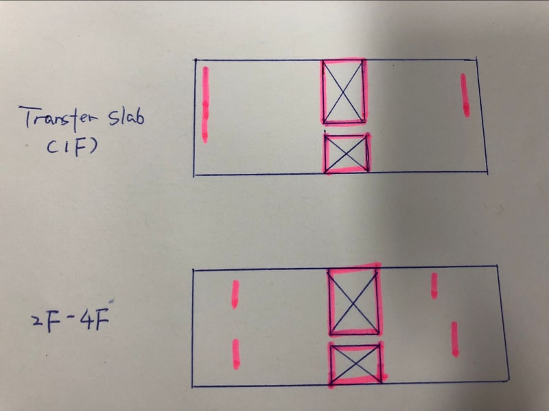
Thanks for replying dik. There are no columns but walls on edge running in x direction which I didn't draw.
 

Hi Agent666. Thanks for your information. There is no columns but walls. Please see pics below. Like I said, as there are voids in the middle I intent to design it as two separated slabs D1 D2 as shown below. I am concerned that if I can use the walls in blue as shear walls for 2-4F. And how do I design the transfer slab for the bending caused by lateral load?
333_f2jtxr.jpg
 
Status
Not open for further replies.

Part and Inventory Search

Sponsor

Back
Top