volcomrr said:
@Aesur, 115mph is vanilla in the middle of North Carolina for Risk Cat II (it's the lowest windspeed in NC and the majority of the US); it definitely ramps up toward the coastline.
Interesting, I didn't realize the 2018 North Carolina Building Code was still based on the 2012 IBC which used ASCE7-10 (which was 115 mph). I was curious because under the 2018 IBC, which uses ASCE7-16, the majority of the US is now 105 mph for risk category II buildings. Don't worry though, they added way more zone factors to make up the difference as normal for needing to sale a new code. I have been looking at getting into the NC market, so good to know they are using old school stuff still!
volcomrr said:
Effective Wind Area: 26' * 26' / 3 = 225sf (sim to stud wind area, L^2/3)
Sawtooth C&C Ult Pressures: Zone 1 = 46.5psf and Zone 2 = 65.1psf
Applied Wind Area at Truss Bearing on Wall = 26' * 2' = 52sf
a = 5.5'
Sawtooth "a" zones occur at each sawtooth perimeter, so at an interior bearing wall, there are back-to-back zone 2's.
Net Uplift (0.6D±0.6W): 5.5'*2'*(0.6*10psf-0.6*65.1psf) * 2 + (26'/2-5.5')*2'*(0.6*10psf-0.6*46.5psf) * 2 = 1384lbs per truss bearing location, or 692plf along interior bearing wall.
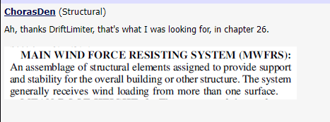
The calculations looks correct to me based on the info provided. So your connection of each truss to the roof would have a reaction of 692 lbs (so something like 2 Simpson h clips) for a combined point load of 1384 lbs on the wall. The wall itself however I would counter is now part of the MWFRS system as it receives loading from multiple C&C elements (trusses), additionally the wall is most likely sheathed so it acts as a larger system, sim to a beam therefore it's trib could theoretically be larger than that used for the trusses, so all you needed to do was use C&C loading for the truss and it's connection to the wall and then can design the wall for a lower uplift based on MWFRS.
Is your dead load really only 10 psf? I rarely see loading that small for roofs, normally in the 17 to 18 psf range once accounting for sheathing, insulation, MEP, ceiling etc?
Another item that is buried in ASCE7-10 but is in a better location in ASCE7-16 is the ground elevation factor, ke. Take a look at it (if I recall it's either in the text of 7-10 or commentary, but it is in there if memory serves) as this can reduce your wind pressures based on your project location elevation above sea level. For instance in my area we see about a 10% reduction due to this and aren't that high of an elevation.
I don't have the time to get too far into the C&C / MWFRS debate at the moment, however historically to my knowledge and based on many wind tunnel studies I have seen and been a part of, C&C is localized wind on an element because while your structure as whole sees the MWFRS wind, a specific smaller area could see a localized higher force, therefore components that take wind directly are normally C&C whereas once you move into the structure and the elements (walls, columns footings, etc) that take loading from more than one member/area you typically transition into MWFRS. Normally I have seen windows, cladding, direct supporting elements (roof joists/trusses/wall studs for out of plane) take C&C and then everything else is pretty much MWFRS. It is also worth noting there are instances where MWFRS can be higher than C&C for things like open structures.

