Continue to Site

Eng-Tips is the largest engineering community on the Internet

Intelligent Work Forums for Engineering Professionals

  • Congratulations KootK on being selected by the Eng-Tips community for having the most helpful posts in the forums last week. Way to Go!

Net Uplift Load Path - Wood Framed Apartment 4

Status
Not open for further replies.

volcomrr

Structural
Sep 25, 2013
11
I'm designing a 4 story wood framed apartment in a vanilla wind zone (i.e. Vult = 115mph). Given the architectural geometry, I'm using a steel framed 2nd floor with slab on metal deck (essentially a podium slab) which supports two additional floors and the roof. The roof happens to be in a sawtooth configuration, which exacerbates the components and cladding uplift loads. With that being said, I have an extreme amount of net uplift at my interior and exterior bearing walls: 708plf ASD net uplift at the roof bearing interior walls based on 0.6D±0.6W using components and cladding loads.

Given the 0.6D part, I need to trace this net uplift all the way back down to my steel podium. Using a holdown on every stud seems asinine; however, cutting a slit in the floor sheathing at each stud to allow a coil strap to pass through does as well. I'm interested in your thoughts on creating a load path down to the podium, whether that be confirming either of the two previous mentioned options or something else creative. Thanks.
 
Replies continue below

Recommended for you

Have you done this sort of project before or not?

You need a complete load path, yeah.

First off, the roof sheathing would be components and cladding, and perhaps the trusses, (until you pass the 700 ft2 area limit?), and the connection into the double top plates and the studs below. If you pass 700 ft2, then it's MWFRS. Second, it's likely that the studs don't meet the definition of C&C (for uplift), so the connection needs to resist C&C at the double top plate, but perhaps not the sill plate, or in the stud. Studs in this scenario would take C&C wind loads from the wall sheathing and tension from the roof trusses which is also C&C, (two surfaces) so somewhere in there that's perhaps not meeting the definition of component and cladding, so it's not required and it's a pathological scenario. Applying both may not do much to the studs, since where I'm at they tend to be 2x6 for insulation more than structural strength, but it may produce more engineered connections than are actually required.

Second, there are reductions to C&C based on tributary/effective area, are you taking those?
 
@lexpatrie: Yes I have done this type of project before, however, not at the mean roof height that I have, nor with a sawtooth roof, hence the higher C&C loads. As for my tributary area to establish the C&C load, I'm using L^2/3, similar to a wall stud; however, the effective area I'm using at the bearing wall is the true effective area: (1/2 span) * 2 sides of interior bearing to get plf. I'm well under 700sf.
 
Your loads seem very high for 115 mph, can you share a sample calc and building section/sketch of the wall including the floor assembly in relation to the wall? I assume you are using ASCE7-10 since you say vanilla wind zone, as in 7-16 115 would be higher risk category or nearer coastlines and uses 105 for many "vanilla zones". I don' believe walls should take vertical C&C, only the roof sheathing and trusses, with the exception of maybe girder trusses, however girders trusses are almost always over 700 sq-ft trib and therefore allowed to be MWFRS. If I understand you correctly you essentially have 3 levels of wood over 1 level of steel, are you accounting for any floor dead load on these walls to offset some of the uplift at lower levels?
 
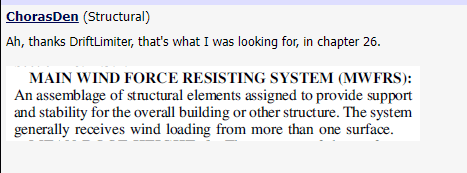
This question seems to come up on this forum in one form or another about every 6 months. Lexpatrie has it right in that yes, you need a complete load path. I also agree that the C&C load is a local load applicable to each component individually. MWFRS is applicable per ASCE 7-16 to members that support/resist (2) or more surfaces. I would consider the connections from stud to foundation to meet this requirement, and thus, I'd design for MWFRS.

Here's a post I have from several months ago that shows the code reference, thanks drift.

Capture1_tanyxv.png
 
Gotcha.

The (bearing) wall takes load based on the actual area, but the wind is based on effective area (L*L/3 for the truss/joist). If that's a wrinkle you can agree with. At some point in the building you're no longer doing C&C loads in the load path, you will still have the end reactions from the shear walls to deal with, and the shear at the base of the wall, but the C&C aspect should go away at some point in the load path based on your interpretation of the definition of C&C. The component and cladding loads are high, bu they are intended to be for the roof membrane, the sheathing, and a bit farther down, not typically going to apply all the way down a multi-story building.

Not sure if this is covered in detail in the Woodworks design example, but if you don't have this already, here it is: Five story design example from Woodworks, Thompson, Dec 2017.
 
@Jayrod, that is exactly what I was looking for! Thank you!

@Aesur, 115mph is vanilla in the middle of North Carolina for Risk Cat II (it's the lowest windspeed in NC and the majority of the US); it definitely ramps up toward the coastline. My bearing walls are 26' on center. For an interior bearing wall supporting roof trusses that are spaced 2' on center:

Effective Wind Area: 26' * 26' / 3 = 225sf (sim to stud wind area, L^2/3)
Sawtooth C&C Ult Pressures: Zone 1 = 46.5psf and Zone 2 = 65.1psf
Applied Wind Area at Truss Bearing on Wall = 26' * 2' = 52sf
a = 5.5'
Sawtooth "a" zones occur at each sawtooth perimeter, so at an interior bearing wall, there are back-to-back zone 2's.
Net Uplift (0.6D±0.6W): 5.5'*2'*(0.6*10psf-0.6*65.1psf) * 2 + (26'/2-5.5')*2'*(0.6*10psf-0.6*46.5psf) * 2 = 1384lbs per truss bearing location, or 692plf along interior bearing wall.

@ChorasDen, I think I disagree. If I'm designing the roof truss for C&C loads, then I'm ensuring each end reaction is stabilized, which has nothing to do with the stability of the overall building. In my case, the end reaction of the roof truss doesn't get stabilized until it get's down to the podium level just due to the limited dead loads that I do have. I think a second level interior bearing wall stud can be considered subject to C&C as it only sees wind loading from one location: the roof. The commentary defines component as "Components receive wind loads directly or from cladding and transfer the load to the MWFRS." Do you design all of your gravity footings for MWFRS even though they may support an effective area less than 700SF of roof? I do.

 
@lexpatrie, I'm looking at bearing walls only; no lateral walls. But, I do understand what you are saying about the wall effective area vs a stud in the wall effective area. However, even using the bearing wall's effective area, it still lands me with C&C loads.
 
volcomrr said:
The commentary defines component as "Components receive wind loads directly or from cladding and transfer the load to the MWFRS." Do you design all of your gravity footings for MWFRS even though they may support an effective area less than 700SF of roof?

I agree with you, I will however point out that the truss design industry as a whole designs their uplift connectors for MWFRS loads instead of C&C loads. They hang their hat on the phrasing of Chorasdens code snip referring to the 'more than one surface'.

 
@TheDW thanks for the link, it's a little mind boggling to read that. Especially hanging their hat on that rational.
 
I've seen and been apart of a lot of these building designs the last 10 years and very rarely seen much more effort than specifying H2.5A's at the end of all roof trusses. Occasionally you'll need something that can take a bit more uplift on a big girder truss, but the truss manuf as TheDW says isn't designing each roof truss for C&C loads.
 
I think the code writing folks and the code reading folks have gotten this MWFRS vs. C&C all confused, trying to use terms about how many surfaces or elements are receiving wind pressures, etc.

If you stand back and think about it - the MWFRS and C&C are both simply from the same WIND. The wind doesn't know whether it is one or the other - it's just wind.

The code properly identifies that, for small effective areas, variability in pressures can be high - with small-area peaks and valleys such that a single nail might "feel" 50 psf wind pressure while the entire plywood sheathing panel sees a bit less...and the wall studs sees even less because the peaks get averaged down by the valleys in the variable pressure distributions.

To me - C&C always controls if your element - whatever it is - has less than 700 sf. effective area.

If an interior column and footing of a single story steel framed building has less than 700 sf. roof area (26 x 26 ft. bays) then that footing is indeed going to see a statistically higher (C&C) wind.

Simply rationalizing that the footing should be MWFRS because it is "separated" from the outer skin to me, isn't rational. The wind pressure that statistically occurs on an element is a real thing and doesn't know that it shouldn't occur because that element has several pieces between it and the outer cladding.


I like lexparties approach
lexpartie said:
...so the connection needs to resist C&C at the double top plate, but perhaps not the sill plate, or in the stud...

Sure if you had a truss that was supported by an isolated column, you want to ensure that column completes the C&C load path, but with a studwall there is a lot more redundancy.

Once you get the load into the double top plate, that element has ability to redistribute the loading. One way to address this would be to check the effective area of the entire wall vs. just the effective area of 1 truss connector.

I think that the spirit of the wind C&C pressures is to do exactly this. We assume that the small area tributary to a single truss connector could reach peak wind pressures. But statistically we acknowledge that if this scenario occurs, most of all of the other trusses are going to be at a lower pressure.
 
volcomrr said:
@Aesur, 115mph is vanilla in the middle of North Carolina for Risk Cat II (it's the lowest windspeed in NC and the majority of the US); it definitely ramps up toward the coastline.
Interesting, I didn't realize the 2018 North Carolina Building Code was still based on the 2012 IBC which used ASCE7-10 (which was 115 mph). I was curious because under the 2018 IBC, which uses ASCE7-16, the majority of the US is now 105 mph for risk category II buildings. Don't worry though, they added way more zone factors to make up the difference as normal for needing to sale a new code. I have been looking at getting into the NC market, so good to know they are using old school stuff still!

volcomrr said:
Effective Wind Area: 26' * 26' / 3 = 225sf (sim to stud wind area, L^2/3)
Sawtooth C&C Ult Pressures: Zone 1 = 46.5psf and Zone 2 = 65.1psf
Applied Wind Area at Truss Bearing on Wall = 26' * 2' = 52sf
a = 5.5'
Sawtooth "a" zones occur at each sawtooth perimeter, so at an interior bearing wall, there are back-to-back zone 2's.
Net Uplift (0.6D±0.6W): 5.5'*2'*(0.6*10psf-0.6*65.1psf) * 2 + (26'/2-5.5')*2'*(0.6*10psf-0.6*46.5psf) * 2 = 1384lbs per truss bearing location, or 692plf along interior bearing wall.
The calculations looks correct to me based on the info provided. So your connection of each truss to the roof would have a reaction of 692 lbs (so something like 2 Simpson h clips) for a combined point load of 1384 lbs on the wall. The wall itself however I would counter is now part of the MWFRS system as it receives loading from multiple C&C elements (trusses), additionally the wall is most likely sheathed so it acts as a larger system, sim to a beam therefore it's trib could theoretically be larger than that used for the trusses, so all you needed to do was use C&C loading for the truss and it's connection to the wall and then can design the wall for a lower uplift based on MWFRS.

Is your dead load really only 10 psf? I rarely see loading that small for roofs, normally in the 17 to 18 psf range once accounting for sheathing, insulation, MEP, ceiling etc?

Another item that is buried in ASCE7-10 but is in a better location in ASCE7-16 is the ground elevation factor, ke. Take a look at it (if I recall it's either in the text of 7-10 or commentary, but it is in there if memory serves) as this can reduce your wind pressures based on your project location elevation above sea level. For instance in my area we see about a 10% reduction due to this and aren't that high of an elevation.

I don't have the time to get too far into the C&C / MWFRS debate at the moment, however historically to my knowledge and based on many wind tunnel studies I have seen and been a part of, C&C is localized wind on an element because while your structure as whole sees the MWFRS wind, a specific smaller area could see a localized higher force, therefore components that take wind directly are normally C&C whereas once you move into the structure and the elements (walls, columns footings, etc) that take loading from more than one member/area you typically transition into MWFRS. Normally I have seen windows, cladding, direct supporting elements (roof joists/trusses/wall studs for out of plane) take C&C and then everything else is pretty much MWFRS. It is also worth noting there are instances where MWFRS can be higher than C&C for things like open structures.
 
JAE said:
I think the code writing folks and the code reading folks have gotten this MWFRS vs. C&C all confused, trying to use terms about how many surfaces or elements are receiving wind pressures, etc.

If you stand back and think about it - the MWFRS and C&C are both simply from the same WIND. The wind doesn't know whether it is one or the other - it's just wind.

The code properly identifies that, for small effective areas, variability in pressures can be high - with small-area peaks and valleys such that a single nail might "feel" 50 psf wind pressure while the entire plywood sheathing panel sees a bit less...and the wall studs sees even less because the peaks get averaged down by the valleys in the variable pressure distributions.

To me - C&C always controls if your element - whatever it is - has less than 700 sf. effective area.

If an interior column and footing of a single story steel framed building has less than 700 sf. roof area (26 x 26 ft. bays) then that footing is indeed going to see a statistically higher (C&C) wind.

Simply rationalizing that the footing should be MWFRS because it is "separated" from the outer skin to me, isn't rational. The wind pressure that statistically occurs on an element is a real thing and doesn't know that it shouldn't occur because that element has several pieces between it and the outer cladding.

I had literally typed this same thing out in response to @TheDW in regards to truss manufacturers using MWFRS loads over C&C but backed it out due to not being able to write it elegantly enough. That being said, I agree with this.

@Aesur, yes my dead loads are very close to 10psf (just shy of it with the architectural materials) and just over it including mechanical, I was a little surprised myself it wasn't somewhere between 15-20psf. I will look into the ke factor; I rarely think about topo or relative elevation unless I'm in a mountainous area of NC. Also good to know that vanilla will be 105! But yes, ASCE 7-16 added a whole lot of other zones, fun stuff. Thank you for your input, I greatly appreciate it!

Also, I greatly appreciate everyone's input on here, both this thread and the thousands of others. I'm a lurker and have been for a decade and maybe have only posted a few times; I need to do better with providing my own input into topics and give back.
 
But to dive in to what feels a bit pathological of an argument, but with a 26 x 26 foot bay spacing, there's a girder that's 26' long both sides, so the area involved in wind uplift for C&C is twice 26 x 26 /3, one for each girder. 446 ft2. Is that how you read it?

How about some nice ballast pavers?

With those wind load effects I presume you're using exposure C, is Wind Exposure Category B justifiable based on a satellite image?

Oh, and are you using the tabulated values or the logarithmic equations?
 
lexpatrie said:
With those wind load effects I presume you're using exposure C, is Wind Exposure Category B justifiable based on a satellite image?
I'm curious how often you get B to work over C. I find that almost 90 percent of projects we do are exposure C due to open patches as defined in the code/commentary. Unfortunately some local jurisdictions we work in actually require us to prove by calc if we use B.
 
lexpatrie said:
But to dive in to what feels a bit pathological of an argument, but with a 26 x 26 foot bay spacing, there's a girder that's 26' long both sides, so the area involved in wind uplift for C&C is twice 26 x 26 /3, one for each girder. 446 ft2. Is that how you read it?

How about some nice ballast pavers?

With those wind load effects I presume you're using exposure C, is Wind Exposure Category B justifiable based on a satellite image?

Oh, and are you using the tabulated values or the logarithmic equations?

Definitely C, there's no way I could meet B with the surrounding terrain. If I had a 26' long girder in a 26'x26' bays, I wouldn't take 2 * L^2/3 for my area on a girder, that would be shooting myself in the foot. I'd use its actual area, and in my case, the bearing wall is 26' long too; so 26'*26' = 676sf, which is still C&C. ASCE 7 commentary only mentions using L^2/3 for members that are along and have a small tributary width (i.e. studs).

Aesur said:
I'm curious how often you get B to work over C. I find that almost 90 percent of projects we do are exposure C due to open patches as defined in the code/commentary. Unfortunately some local jurisdictions we work in actually require us to prove by calc if we use B.
Same, I rarely find anything that meets B . There's either a field or something in at least one direction that nixes B.
 
lexpatrie,
I may have muddied the waters with the 26 ft. bay example - yes, the "effective" area would be applicable and perhaps a much smaller bay would qualify for C&C in that case.


Status
Not open for further replies.

Part and Inventory Search

Sponsor