Continue to Site

Eng-Tips is the largest engineering community on the Internet

Intelligent Work Forums for Engineering Professionals

  • Congratulations KootK on being selected by the Eng-Tips community for having the most helpful posts in the forums last week. Way to Go!

Neutral Current for CAPACITOR Unbalance Protection 1

Status
Not open for further replies.

afzumannu

Electrical
Jul 1, 2011
93
Dear Engineers,

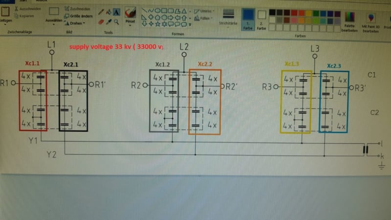
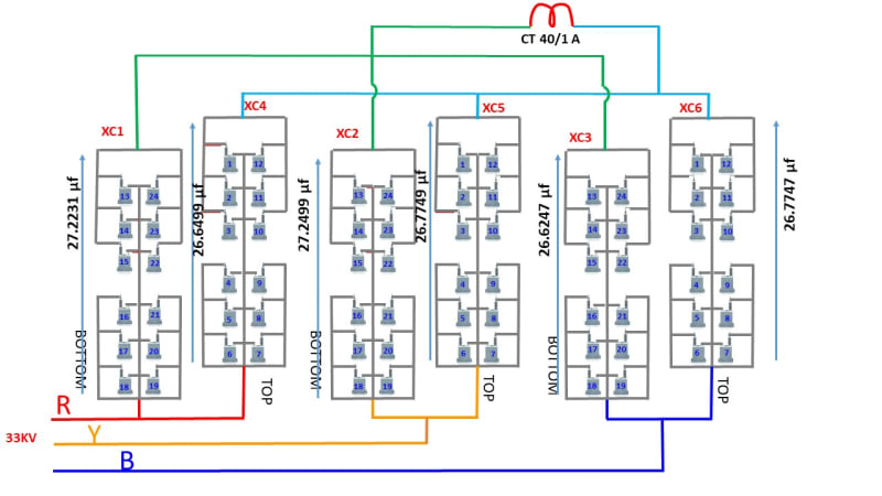
We have Filter bank line voltage is 33 KV ( 33000V), ungrounded double star connection. capacitors are connected series parallel group. each phase one row is connected to star1 and other row is connected to star2 , unbalance CT is connected in between both star point. i want to know what is the formula for neutral current flow so can understand the % of unbalance.
i know one formula that is Iunb = ( I1+I2+I3)-(I4+I5+I6), I1,I2,I3 is one star side each phase, while I4,I5,I6 is other star side. also Iunb = Un/Xc, so i will apply the values in this formula which. I have recorded the values for Xc1 = 27.2231µF, Xc2 = 27.2499, Xc3 = 26.6247 ( one group), Xc4 = 26.6499,Xc5 = 26.7749, Xc6 = 26.7747(2nd group), hence Xc=1/2πfc, here i want to know from you guys What is Un here is it 33000 V supply voltage? or individual Capacitor name plate rating, 15000V, 459 KVAR, or someone can calculate the neutral current here, any other formula let me know.
 
Replies continue below

Recommended for you

capacitor_bank_irceuc.jpg


please check the attached jpg file
 
There is no meaningful current in the CT under normal conditions, not even if the 33kv is unbalanced. Current does flow in the CT when:
-one of the capacitor cans becomes shorted, loses some of its capacitance or becomes open.
(do the cans have internal fuses?)
-manufacturing tolerances or temperature effects result in slightly different impedances amongst the 6 branches

You want the unbalance protection to see one can open but not see the tolerance/temperature effects. Work out the current unbalance for the largest legitimate impedance unbalance and the current unbalance for the least impedance unbalance from a failure. The difference is the area where the unbalance protection relay can be set.

Bill
 
Thanks Bill for reply.

i know that it will fail if anyone can fail and impedance change, actually every month we are checking all the capacitors capacitance µF value and recording. so that before starting the Equipments i should know the unbalance condition even minor also based on capacitance. sure there is formula for calculation of this Iunb current, please let me know that what equation should be for Iunb, Circuit diagram already attached, before capacitor bank also Reactor connected in series. please reply
 
I believe if you download the instructions for SEL-487V relay you will find a good discussion. Additionally there are several application guidelines discussing this
 
Thanx DTR2011,
I Downloaded the SEL-487V relay Manual but didnt find the current calculation
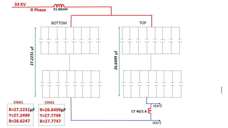
please i want to know the how much current flowing in Neautral point if we know the capacitive reactance, so that i can know the % unbalance before starting the Filter bank. every month we are stopping the Filter Bank and recording the capacitor value. also important that before that 21.66mH inductor is connected in series with capacitor bank. Sure there is Formula but i am not getting that. please help
 
A quick Google for "How do you solve an unbalanced 3 phase system?" brought up this video, . I didn't go through it and I haven't done matrix math since college but I think putting 3 different capacitive impedances into it will give you the voltage at the star1 neutral. Then that would have to be worked against the star2 calculations.

Excel's Data/Goal Seek is an alternate way to get around some of these higher mathematics. Have it vary, say a neutral CT current figure added to the normal current and worked back through the 6 branch impedances. Goal Seek this until the 6 errors in the absolute voltage calculated at the top of each branch versus the actual supply all add to zero.... well some calculation like that.

Oh, here's another Google search term that may help, "capacitor bank unbalance current calculation" .

Bill
 
Addressing to your original question: you can't use neither the line voltage 33 kV directly (33/√3) nor the capacitor voltage 15 kV. If all the branches were exactly equal to each other, you could use the line voltage to obtain the currents, but in that case you wouldnt have any unbalance and there would be no point. Because you have some unbalance in the center of the stars, the voltage applied to each branch will be different from the line voltage.

Check here, on page 11, if you already have the line currents you can calculate the unbalanced current between stars.

Now, If you don't have the line currents, there is no alternative, you must do the math and solve the circuit. It seems there is no formula to calculate it right away.
I would start with something like the attachment (sorry for the awful writing). Please check for any errors, I did it in a hurry.

Good news is that you can assume that the line voltages are balanced and symmetrical, because of what Bill said.
Bad news is that you need to solve the circuit with the vectorial values of voltages and currents (you could simplify ignoring the resistances of the circuit and just deal with reactances).

Hope it helps.
 
 https://files.engineering.com/getfile.aspx?folder=5fbbf748-32bd-45c7-bb50-f36757ca7901&file=IMG_20200420_183652.jpg
I think argotier has found the answer. Formula (13) at the bottom of page 12, simplified a bit in terminology is:
Unbalance current = normal phase current/2 x [(C1f-C2n)/(C1f+C2n)]
where C is capacitance of one branch, 1 & 2 are star 1 & 2 and f & n are faulty and normal conditions.

We can take this further by just counting the cans. afzumannu has 4 in parallel by 4 in series so the capacitance is 4 cans parallel divided by 4 sets in series thus equal to 1 can under normal conditions. When 1 can fails open this becomes 1/[1/3 +1/4 +1/4 +1/4] which equals 0.923. The unbalance is then 100% phase current divided by 2, times [(0.923-1)/(0.923+1)] which is 50% times 0.04 or a 2% unbalance current for a single can failure.

Bill
Ps: it's late, errors & omissions are excepted :)
 
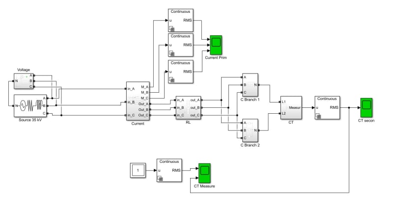
You can use Matlab Simulink for calculating unbalance current. Simulink calculate very accurately. Recently I calculated unbalance current for bank of capacitors 10 kv by Simulink, result was very similar to real unbalance.
Can you give more information about resistor, reactor, I will try to calculate unbalance.
 
Dear Beyond,

thanx for reply,

I don't have idea about Matlab simulink, but we have LC filter the inductance is 21.66mH/phase, I am attaching the real arrangement diagram which is easy to understand but it is for one phase only, another phase also same arrangement and connecting to star point..only Capacitance value I measured which i mentioned for all phase, waiting for your reply, Supply Voltage is 33 KV
150HZ_sln7dw.jpg
 
thanx@ beyond

your answer is very similar and correct. I appreciate. please share the calculation method or formula also.
 
It isn't a formula, it's a model which was created in Matlab Simulink. If you have Matlab, I can send you .slx file.
Untitled_bhaboi.jpg
 
yes, i just download Matlab simulink in my mobile without licence. please send the link if it can work.also put the same value as i mentioned it.

but sure there will be logic behind this as it is giving the accurate answer... sure it has the calculation formula from there we can get the same result. i am waiting for reply
 
not opening this file,
give me the logic behind this...who create this model sure they put the logic also.
 
afzumannu, I created this. It's is just model with your parameters.
 
@Beyond,

what parameters you applied, I Mean supply voltage, capacitance value, inductance value, frequency or any others?

just please share your calculation. so i can get the formula based on imepedance

 
Status
Not open for further replies.

Part and Inventory Search

Sponsor