Dear Mick,
I note you have updated the geometry scale factor to import the geometry in mm (not in inches, like before), good!. But still more things are "incoherent", for instance:
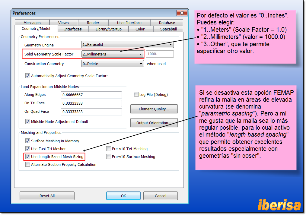
• The material properties are in PSI, not in MPa, this is because the material library you are using (by default, the file "material.esp") is in inches, pounds, ºF, etc.. Take a look to my website to learn how to configure FEMAP Preferences, this is the initial setup to be done in any FEMAP installation:
• I note you has prescribed an enforced displacement of TZ=40mm, and you are done!!. Well, if you do not constraint the TZ DOF as well then FEMAP will complaint when writing the NX NASTRAN file input with the following error message (in RED):
Node XXX, DOF 3 is not constrained but has Enforced Displacement applied.
And the NX Nastran solver will ignore at all the enforced displacement.
Take a look to the NX NASTRAN Users' Guide and search for enforced displacement, you will find the following:
Enforced Displacements at Grid Points (SPCD, SPC)
There are two methods available to you for specifying an enforced displacement at a component. The first method is to enter the value of the enforced displacement directly on an SPC entry.
[highlight #FCE94F]
The alternate method to enforce a displacement at a component is to use the SPCD Bulk Data entry. The SPCD entry is actually a force, not a constraint, but it is used in conjunction with an SPC entry to enforce the displacement. When you use an SPCD entry, internal forces are computed that are applied to the structure to produce the desired enforced displacements[/highlight] (this is the method that runs FEMAP).
• Also the mesh created in the FEMAP model is extremely coarse, you need minimum TWO ELEMENTS in the wall thickness to account for the gradient stress in the walls. And the problem should be solved as NON-LINEAR (SOL106) because the wall thickness is 5 mm and you plan to prescribe an enforced displacement TZ=40mm, then a linear static (SOL101) is useless, only colors.
Also, you must learn to mesh with HEX8 elements, in nonlinear analysis the model size is critical, using HEX8 elements instead TET10 means a reduction on model size (for the same element size) of 8 to 10 times smaller!!. And accuracy of HEX8 elements is excelent, conpared with tetraedral elements.
In my blog you have videos to learn how to mesh with HEX elements (see
For instance, with very low effort the body of the spring can be meshed with hexaedral elements with two elements in the wall thickness (element size = 2.5mm), the model size is 9936 nodes, very small!. For the rest of components you can use the GLUE face-to-face condition and mesh with HEX elements as well, TET meshing (in nonlinear analysis!) should be used the minimum as possible.
• And finally, if you plan to consider surface-to-surface contact (no penetration) between the faces of the spring, then you need to run Advanced Nonlinear Analysis module (SOL601) because the basic nonlinear solver of NX NASTRAN (SOL106) do not support surface-to-surface contact "no penentration".
In summary, before starting the house for the roof, better first run to the multiple FEMAP examples you have in the program, go to HELP > EXAMPLES and try to run ALL examples to understand how to deal with the Finite Element Method (FEM/FEA). I am very sorry, but this is FEA, enjoy!. Of course, ask for a training course to your FEMAP reseller, this is basic!.
Best regards,
Blas.
~~~~~~~~~~~~~~~~~~~~~~
Blas Molero Hidalgo
Ingeniero Industrial
Director
IBERISA
48004 BILBAO (SPAIN)
WEB:
Blog de FEMAP & NX Nastran:


