Continue to Site

Eng-Tips is the largest engineering community on the Internet

Intelligent Work Forums for Engineering Professionals

  • Congratulations KootK on being selected by the Eng-Tips community for having the most helpful posts in the forums last week. Way to Go!

No lateral load path - blocking missing above top plate 1

Status
Not open for further replies.

BubbaJ

Structural
Mar 18, 2005
163
Before I deliver some bad news to the contractor, I wanted to reach out to the group to see if there were any other options to explore.

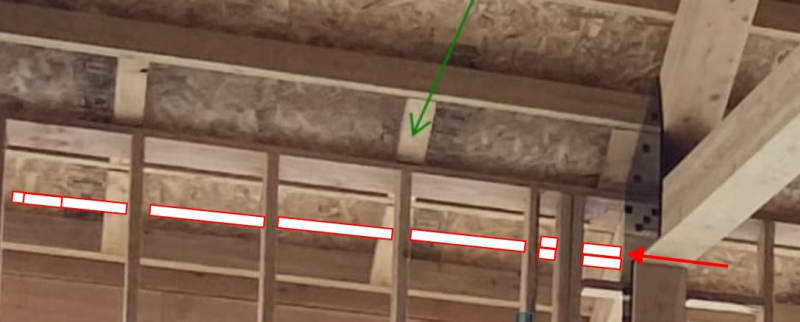
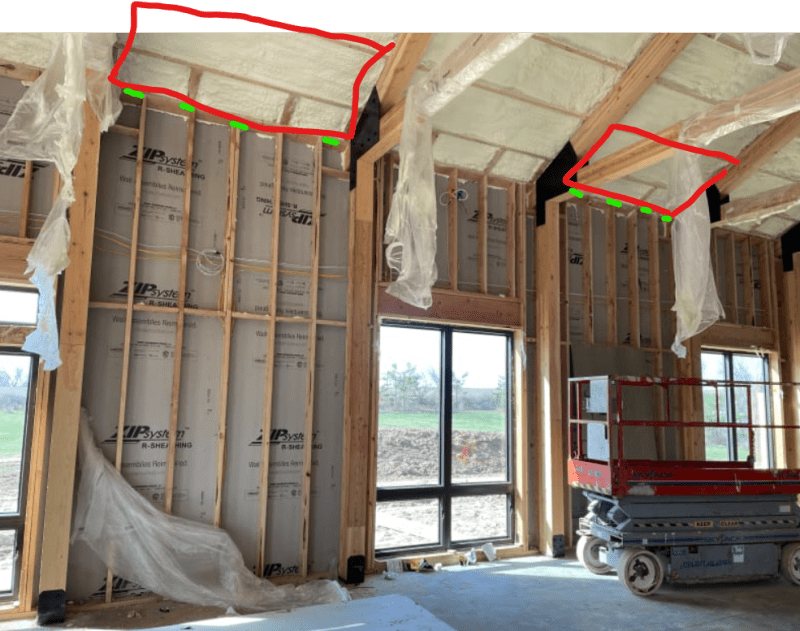
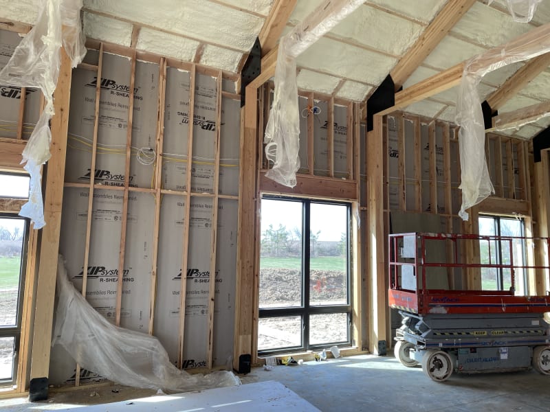
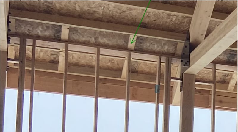
The framer took it upon themselves to ignore the drawings and the inspector noticed. Which is good, because there is no longer a continuous load path from the roof diaphragm to the shear wall. As you can see from the photos, they left out the blocking above the top plate. There are LVL trusses and columns, but they only carry gravity loads. By the time I was alerted to the problem, the roof was on and the spray foam insulation was completed.

I do not see any other solution than having them add the blocking, which will mean removing insulation and possibly roofing. Does anyone else see a different solution?
IMG_5983_whed4u.jpg


South_wall_ut6ury.jpg
 
Replies continue below

Recommended for you

Is the shear too much for the trusses to discretely deliver the load to the shearwealls?
 

The load at the truss would be around 1680 lbs. So, are you thinking some sort of Simpson clip from the truss to the top plate of the wall?

I will also have to verify they used blocking between the purlins above the trusses.....
 
Properly connected, that piece that the green arrow points too could transfer some load. It looks like there's some shims under it though which might preclude a meaningful connection. The top of the wall is level and not raked, right? Maybe a one of those simpson clips that is foldable could make a connection.
 
This is speaking to a version of XR's idea if you can still fasten some blocking to the shear wall sheathing. You'd still have to:

1) Get the load out of the purlins and into the end of the truss.

2) Through the truss and into the blocking.

3) Perhaps provide tension strapping on the blocking if you can't get the job done in compression alone.

This is one of those issues that I'd almost prefer not be brought to my attention since I'm sure that's it's fine in real life unless you're high seismic. And even then...

C01_h3mnqp.jpg
 
You might even be able to get that blocking right up against the underside of the top plate if the truss would still bear into it.
 
kootk said:
Properly connected, that piece that the green arrow points too could transfer some load

The piece is a 1x and not connected to the roof sheathing.

kootk said:
This is one of those issues that I'd almost prefer not be brought to my attention since I'm sure that's it's fine in real life unless you're high seismic.

There have been soooo many things and I have to correct or sign off on all of them or the inspector will not let them pass. Some of the things have been issues that were just plain wrong, others are just nit picking. For instance, the architect called out a plumbing wall to be 2x6 (standard note for them), it was framed as a 2x4, the plumbing fit. The inspector wanted it changed or wanted the drawing changed.
 
BubbaJ said:
The piece is a 1x and not connected to the roof sheathing.

I know. The load would come in through the purlins which are connected to the sheathing. I'm not saying that this path is great, or even advisable, but it's a path.

I celebrate rigorous inspection work, even if it's a hassle sometimes. The pros outweigh the cons I think.

 
This would probably mess up the finished ceiling detail, but could you do something with plywood subdiaphragms between each bent? Maybe just fastened to the 2 purlins adjacent to the top plate. Then intermittent metal clips to take the load from the sheathing to the top plate.
 
bones, with the price of plywood they could re-roof the building. LOL.
 
Could you put some sheathing on the underside of the overhang to bring the load back to the shear wall?
 
IceNine said:
Could you put some sheathing on the underside of the overhang to bring the load back to the shear wall?

It's not a bad idea. You don't need to do it for the whole length. Just a few selected bays right above the solid shear walls.
 
This is what I was getting at. Simlar idea as IceNine suggested, just on the inside.

Screenshot_2021-05-13_193749_xkgdab.png
 
I think the flatwise 1X's could transfer shear to the top of the shear wall--if connected to the shear wall. Perhaps gouge out a little of the insulation, put in a connection, and re-foam?

DaveAtkins
 
This is not worth your design time to come up with some load path through a 1x... The contractor was more worried about being "green" than correctly framing the building. A lot of the above ideas assume there is adequate nailing to transfer the diaphragm shear into alternative members and I doubt that is the case.

I disagree with the idea that this is probably fine, a continuous load path is more important than any fancy calcs.

Make them add the blocking at the top of wall.
 
“The detail has not been constructed in accordance with our drawings. Please forward sketch details of your proposed remedial action for our consideration.”

Why should you be out of pocket for someone elses f€&k up?!
 
Also, none of the suggestions address the now missing chord and collector elements.
 
Harbringer said:
A lot of the above ideas assume there is adequate nailing to transfer the diaphragm shear into alternative members and I doubt that is the case.

For my proposal, that's kind of what I was getting at with the statement below. That said, out of necessity, one really has to assume some minimum level of competence on the part of the OP with respect to their ability to prosecute the details of the load path both upstream and downstream of the proposed solution. If OP designed the diaphragm for the requisite shear capacity to begin with, I assume that shear capacity remains and that all that remains is to establish boundary nailing between the diaphragm and whatever winds up being the boundary element. Not that that's going to be an easy thing.

KootK said:
The load would come in through the purlins which are connected to the sheathing.

Harbringer. said:
Also, none of the suggestions address the now missing chord and collector elements.

Again, and speaking only for myself, that had more to do with limiting the scope of my proposal rather than:

a) failing to recognize the requirements for boundary elements or;
b) there not being any options for boundary elements.

Depending on the approach that OP takes with the blocking, some options for boundary elements might include:

1) Using the top plate if strapping can straddle the trusses.

2) Using the top plate without strapping if every wall is a shear resisting panel and would suffice in its own right.

3) Using the facia structurally, likely by adding some tension strapping at the butt joints.
 
MIStructE said:
“The detail has not been constructed in accordance with our drawings. Please forward sketch details of your proposed remedial action for our consideration."

While that's certainly fair, I suspect that it would not be viable in many situations given that:

a) Many contractors wont be too excited about engaging a 3rd party engineer to work on the issue for them.

b) The odds of a contractor generating their own solution to a lateral load path issue that would meet OP's requirements is surely pretty close to nil.

I worry that OP would end up wasting a bunch of back and forth time on vetting the contractors proposals and still wind up doing it himself.
 
If each wall segment is effectively a shearwall, the load should be able to be funneled into the truss top chord by the last purlin (with appropriate clips). The truss appears to be tight against the wall top plate so it should be able to transfer through direct bearing.
 
Status
Not open for further replies.

Part and Inventory Search

Sponsor