Eng-Tips is the largest engineering community on the Internet

Intelligent Work Forums for Engineering Professionals

Norway bridge collapse - Part 2 2

Status
Not open for further replies.

Sym P. le

Mechanical
Jul 9, 2018
1,032
0
36
CA
Norway bridge collapse (Part 1)


The latest on the Tretten bridge collapse from Norwegian Safety Investigation Authority (English site)

- Sub-report 1 on the bridge collapse at Tretten on 15 August 2022 - Published 15.08.2023, 3.7 MB
- Appendix B - 33.5 MB
- Report film for download (188 MB)

These are Norwegian language links though Sub-report 1 includes an English Summary.

A further report is the works:

NSIA said:
Sub-report 2 will focus on bridge management and follow-up of Tretten bridge throughout the bridge's life cycle, based on the main findings identified through the technical investigations.

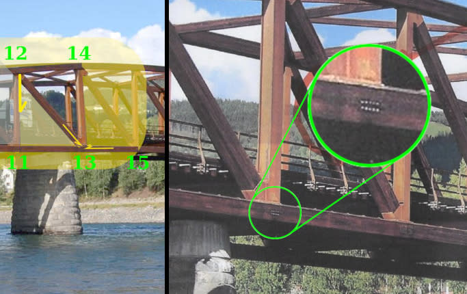
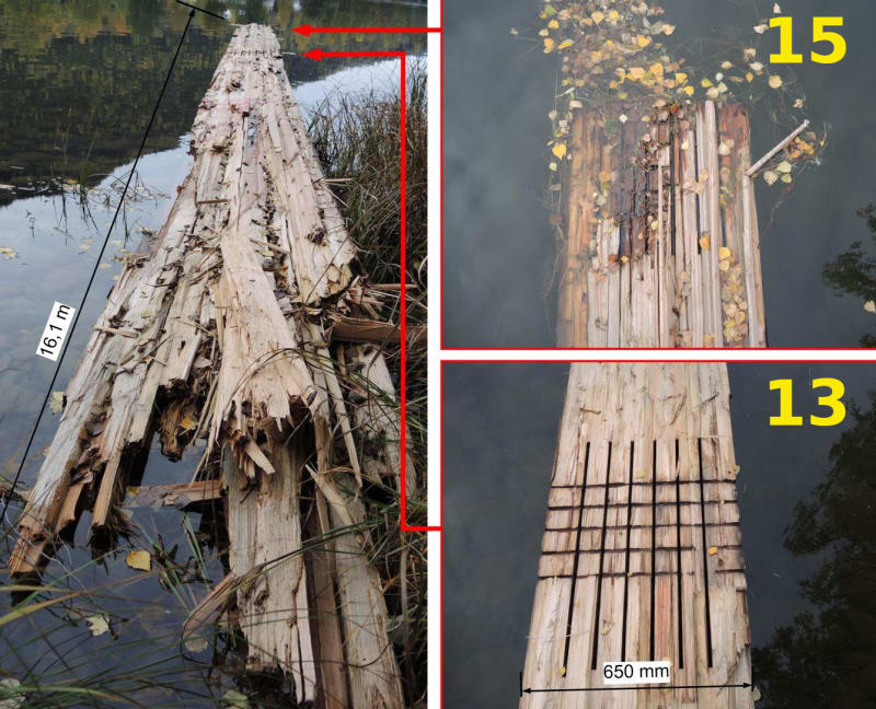
Note: In the reports, nodes are designated A for upstream (north truss) and B for downstream (south truss).

 
Replies continue below

Recommended for you

Summary below.

Norway_Brd_Summary_yyiqbh.png
 
It seems they are grasping at straws. Since they can't pin it on a single known over-capacity load, they go for fatigue. In other words nominal traffic wore out the connections in ten years? That is equally unlikely.

The report expends too much effort on computer graphics espousing their theories as though that will lend credibility to their conclusory leaps. They open by stating they have considered many possible causes but list none of them.

Interestingly, a 100 ton load was moved across the bridge in April 2015. What happens to node 13 when a 100 ton load moves across the west span? That too is an easy lab test.
 
Sym P. le said:
It seems they are grasping at straws. Since they can't pin it on a single known over-capacity load, they go for fatigue. In other words nominal traffic wore out the connections in ten years? That is equally unlikely.

The report expends too much effort on computer graphics espousing their theories as though that will lend credibility to their conclusory leaps. They open by stating they have considered many possible causes but list none of them.

Interestingly, a 100 ton load was moved across the bridge in April 2015. What happens to node 13 when a 100 ton load moves across the west span? That too is an easy lab test.
I must admit that your authorities tone and your contrary opinion started to have me agreeing with you before I had even looked at the linked source material.

After looking at it doesn't seem like your comments align well with their conclusions. Block shear failure is called out specifically. They haven't just scatter gun the shot at fatigue, they have specifically zeroed in on a particularly type of failure in a particular area. Some materials (timber) have a significant difference between their single event capacity and they 100,000 cycle capacity.

I don't see the obvious issue with their conclusion that you see.


**Feel free to come back at my fighting words. I can't say I'm an expert in the failure analysis of timber bridges!
 
Yes, I agree that fatigue is likely involved. "Nominal loading over ten years" defines fatigue loading quite well. But material degradation is also likely a factor, along with design error.
 
Thanks for weighing in. I have no doubt that block shear occurred as a result of fatigue. My question is why?

We generally have a very robust discipline that ensures our structures don't fail catastrophically or if they do, they give ample warning. To pass off vague assertions as an engineering review is an insult to intelligence and no amount of computer graphics will assuage that. It lacks inquisitive tenacity and is just plain lazy.

In this case, there is an engineering flaw that will lead to fatigue of the identified connections at nodes 14 and 15. A load on the west span will flex the lower chord at node 13 while simultaneously driving the pin connection horizontally into it, the perfect conditions to split the chord. At the same time, movement of the steel U frame at 13 will cause rotation at the 14/15 connections. (Note: The U frame is not fixed to the support or the road deck so it's free to slide between them. The diagonal transfers its horizontal load to the lower chord through the U frame and thus, the pins.)

Facebook_image_of_node_13_ebzme2.jpg


I don't see much in the report to build my theory other than a photo of the split lower chord. It's length spans the distance from node 11 to 15 and the split is clean and even from 13 to 15. The report suggests this split was caused by downward movement at 15 but I don't find that compelling.

Lower_Chord_recovered_a8znyw.jpg


I don't think there is anything intentionally lacking in the report, just that it lacks tenacity.
 
From Appendix B,

page 51 said:
Fra inspeksjon av skadde brudeler har trolig første brudd skjedd i tilknytning til en vertikal mellom knutepunktene 15 og 16 (T15-16). På disse vertikalene hadde både overgurten og undergurten en skjøt, ...

From inspection of damaged bridge parts, the first break probably occurred in connection with a vertical between nodes 15 and 16 (T15-16). On these verticals, both the upper girth and the lower girth had a joint, ...

What is it about the damaged bridge parts that flags this as the first break. It is one thing to suspect this node as problematic, and I agree it could be, but another to posit this as the initiation site. To me this is a leap.

page 51 said:
Fra kolonnen til høyre i Tabell 27 i vedlegg F, sees det at 3 diagonaler har fått (beregningsmessige) utmattingsskader, sortert etter skadeomfang: diagonal 7, 6 og 16. Diagonal 7 peker seg ut som den suverent mest utsatte for utmatting, og for denne diagonalen er levetiden langt overskredet. Diagonal 6 har også overskredet sin levetid med god margin, mens diagonal 16 anses som å ha nådd sin levetid.

From the right-hand column in Table 27 in Appendix F, it can be seen that 3 diagonals have suffered (calculated) fatigue damage, sorted by extent of damage: diagonal 7, 6 and 16. Diagonal 7 stands out as the supremely most exposed to fatigue, and for this diagonal, the service life is far exceeded. Diagonal 6 has also exceeded its useful life by a good margin, while diagonal 16 is considered to have reached its useful life.

Diagonal 7 is by far most exposed to fatigue by these calculations yet the catastrophic failure occurs across 6.

page 219 said:
Fra kolonnen til høyre i Tabell 28, ses det at 3 diagonaler har fått (beregningsmessige) skader av betydning fra utmattingsbelastning, nemlig diagonal 6, 7 og 16. Rekkefølgen av de skadde diagonalene er presentert i Tabell 27. Også her er diagonal 7 langt over grensen for sin levetid, men hvis vi antar at strekkfastheten i diagonal 7 er 20 % større enn i diagonal 6, er det tenkbart at diagonal 6 feiler pga. utmatting før diagonal 7, siden diagonal 6 i Tabell 27 har større kadeindeks enn diagonal 7 i Tabell 28.

From the column to the right in Table 28, it can be seen that 3 diagonals have received (calculated) significant damage from fatigue loading, namely diagonals 6, 7 and 16. The order of the damaged diagonals is presented in Table 27. Here too, diagonal 7 is far above the limit of its lifetime, but if we assume that the tensile strength in diagonal 7 is 20% greater than in diagonal 6, it is conceivable that diagonal 6 fails due to fatigue before diagonal 7, since diagonal 6 in Table 27 has a larger causeway index than diagonal 7 in Table 28.

"... but if we assume that the tensile strength in diagonal 7 is 20% greater than in diagonal 6 ..."

Seriously? I suppose I need to translate some more text but I'm already finding fatigue theory tiresome, or at least this application of it. As I said, they seem to be grasping at straws.
 
MechinNC said:
Why use wood at all?? The steel or iron bridge lasted, what 100yrs (??).

Seems foolish.
And timber, brick and concrete bridges have lasted many centuries and sometimes millennium.

I'm sure somebody at some stage asked why use steel at all?
 
Where did this notion that 'wood is bad in tension' come from? There's nothing wrong with wood in tension. Depending on the size, visually graded southern pine lumber is has a higher allowable stress in tension than it does in compression (when fully braced and not subject to buckling, no less).

Here's a decent example of a long span wood bridge using wooden tension members. It's only 157 years old.

Is wood always the best material? No! But neither is steel or concrete or any other material. They each have their place - local material availability, local labor specialty, local values and what they want to do to embody those, and any other number of things play into the economics and social impact of bridge and building design.

This bridge could have done quite well, but the designer failed to recognize a failure mode as it wasn't part of the enforced design standard and, once it was recognized, the authorities failed to act to make the necessary modifications. To me, this sounds like less of a 'wrong material' issue and more of a 'failed to act with due haste' issue.
 
It might also have been a "build the structure before we adequately test the design" issue.

It would have been quite something if the Tretten bridge had been done as a wood lattice truss. The longest span of the Tretten bridge WAS 230 feet. The longest span of the above linked bridge IS 204'. A Howe truss would have been fetching, also! Probably would have used less steel, also.


spsalso
 
Strength & Properties Class C16 C24
Bending parallel to grain (N/mm2) 5.3 7.5
Tension parallel to grain (N/mm2) 3.2 4.5
Compression parallel to grain (N/mm2) 1.8 7.9
Compression perpendicular to grain (N/mm2) 2.2-1.7 2.4-1.9
Shear parallel to grain (N/mm2) 0.67 0.71
Modulus of elasticity mean (N/mm2) 8,800 10,800
Modulus of elasticity minimum (N/mm2) 5,800 7,200
Characteristic density (kg/m5) 310 350
Average density (kg/m5) 370 420

This is the material properties we use in Europe for structural construction wood.

I just add them for info.
 
Exactly. That video shows a classic splitting failure mode. Caused by either bolts too small or end distances to short.

People that deal with bolted joints in metal structures are not aware of the failure modes other than bearing (compression at the hole edge) that can occur with wood and composite materials - net section, shearout, cleavage - and those failure modes result in two part fracture, not a load redistribution with bearing failures.

To my composite material eyes, the timber bridge design had way too many fasteners spaced way too close together. If you look at the old wooden covered bridges, the bolted connections are much different.
 
The excerpt below suggests they need to skip the site review and send out the design drawings to some PHd types to study for several years. This seems like a case where the connection looks good until it doesn't.

TrettenBridge_z36hfn.png
 
I think that it should be remembered that the most important goal of the analysis of this bridge failure is to eliminate any blame for any of the entities involved. That can take a good bit of time and effort--it's not as easy as it looks!


spsalso
 
The 2016 review finding of "No Significant Errors" is most likely with respect to the code of construction.
Brad805 (Structural) copied the reports conclusions which indicate the current code (in 2016) would have required stronger joints.
So how does the finger pointing go when the engineer uses a code of construction specified by the AHJ and it turns out to be wrong?
 
Status
Not open for further replies.
Back
Top