Eng-Tips is the largest engineering community on the Internet

Intelligent Work Forums for Engineering Professionals

NX 12.0.0.27 - Extruded surface creates a convergent body 3

Status
Not open for further replies.
Replies continue below

Recommended for you

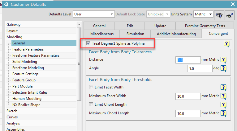
in NX12.0.2 there is a new customer default , "Treat degree 1 splines as polyline".
If the extruded object is a degree 1 spline, the result should then become a convergent body. ( the dialog does not say this but it is the result.)
i assume that you have to create the extrusion again after toggling off this customer default. You need to restart NX after the switch.
image_l0xzwf.png


Regards,
Tomas

Edit: I see that the same option exists under Preferences - Modeling- Convergent.
 
Hi Toost,

thanks for your quick response.
In preferences the check box, you are referring to, was already checked when I extruded the surface.
What has a convergent body to do in an extrude operation?

what else can be done?

Thanks.
 
I do not know the benefit of this one. ( i'm curious as well.)
I guess that you need to re-extrude without this option ticked to get "a normal solid" .

Convergent bodies is a pretty smart way of working with point clouds.
Instead of treating the point cloud as discrete points that one has to map surfaces and planes to, NX can now treat the point cloud as a "mud blob", on which you can perform regular boolean operations.


/ Tomas

 
I haven't had the misfortune opportunity of running into this convergent/faceted model combined with math-based model BS scenario yet. Is anyone else concerned at all that we're able to take 2D math and the result could be a non-math model without any sort of a warning, etc.? I get the feeling this faceted modeling crap capability should be in its own application to prevent this sort of crap event from ever happening.

Also, my NX12 docs state that the "Treat 1 Degree Spline as Polyline" setting in Modeling Preferences is a Realize Shape preference:

Treat Degree 1 Spline as Polyline

Select this option when working with NX Realize Shape to automatically have single segment splines treated as polylines.
This eliminates having to explicitly extract a polyline from a single segment spline.

Thoughts?

Tim Flater
NX Designer
NX 11.0.1.11 MP8
GM GPDL 11-A.3.3
Win7 Enterprise x64 SP1
Intel Core i7 2.5GHz 16GB RAM
4GB NVIDIA Quadro K3100M
 
I've had the misfortune of having it happen and not realizing it for an hour or so. Luckily when you have to redo your work its faster the 2nd time around...
 
I had the same experience in 12.0.1 and called GTAC about it. IMO it should be unchecked OOTB and was probably just an oversight.

[wink]

NX 12.0.2
 
> I get the feeling this faceted modeling capability should be in its own application

Not going to happen. The whole point of Convergent Tech (CT) is to allow mixing of facetted and "classical" objects within the same model. If there were two separate modules, which one would you use to perform a boolean between a facetted object and a classical (curvy) one??

If anything, the facetted and curvy worlds are going to get even more intermixed. Pretty soon, we'll have bodies in which some faces are faceted mesh surfaces, and some are classical curvy surfaces. You get to choose, on a face-by-face basis, whether you want to expend the time/effort to replace each mesh surface by a classical curvy one.

If you extrude a spline with degree 1, getting a CT mesh surface is somewhat reasonable. It's exactly the same shape as you'd get with a b-surface, and it requires a lot less space. The only problem is that some functions don't yet work on convergent bodies, but the list of non-supported functions gets smaller with every release.

Characterizing some surfaces as "math" and some as "facetted" is misleading. They are both "math". The only thing that has changed with CT is the addtion of a new surface type -- a facetted mesh surface.
 
BubbaK,

For the sake of clarity and lots of unnecessary typing, when I say solid or solid body I am referring to a traditional solid body that's not faceted. Also, my reply might seem like a novel only because I want to be clear and not pass along any misinformation which might in turn lead others astray. With all that said and as Jules (Samuel L. Jackson) from Pulp Fiction said, "please allow me to retort"...

First off, I have a bad habit of referring to solids (see above) as math. NX also lends to that habit of mine by historically not allowing a faceted model to be selected if your filter were set to Solid Body (until Convergent Modeling came along). That's why I inaccurately referred to a faceted model as not math. Sure, I'm a bit edumacated and realize they're both math - just like I'm fairly certain you realize a faceted body is nothing more than a collection of planar faces approximated from a solid - there aren't edges in the same sense that the solid has (yes, the edges are there between the triangles but those aren't representative of real edges - like the edges of a hole). There, can we agree up to this point? I hope we can also agree they are completely different body types regardless of what Convergent Technology (CT) brings - because nothing up to NX12 is going to change that either. Solids will remain solids and facets will remain facets, even with the introduction of CT - and this is where we might disagree, so I thought it would be prudent to ask GTAC the following:

Q: Is a convergent model a math model (meaning a traditional solid body) or is it a faceted model or a combination of both?
A: It seems the intent of this new technology was to eliminate the steps during reverse engineering where surfaces were generated on the faceted geometry. While the convergent body does not become analytic, it is selectable for feature based modeling. It is my understanding that the convergent body is still a faceted body. It does, however, now become selectable when selection intent is set to solid body (for enclosed volumes) and sheet bodies for surfaces. Since the convergent bodies are recognized as such, they can be used in Boolean operations and I was able to apply features directly on the convergent geometry.

Q: How would a Boolean operation work between a math model and a faceted model using convergent modeling? Would the math model be converted to convergent or both models converted to convergent or neither?
A: It is also my understanding that when a Boolean involves a convergent body that the results will remain convergent.

Before going any further - the GTAC employee response isn't to be read as Siemens' official stance, blah, blah, blah - it's just a question and his answer. Maybe that's not definitive enough for some, I don't know. I'm a 20+ year user and this employee isn't known for blowing smoke, so take it for what you will. I trust that this person is accurate and isn't misleading.

Reading the Q&A above, it sounds to me like a convergent model is still a faceted model and there isn't any mixing between solids and facets at all (at least on a solid). CT is apparently allowing features to be used on a faceted model and that's it. Should you try to mix between the two, regardless of which is the tool or target, the result will end up being faceted at this point in time. I didn't ask about future plans because that's utter speculation and Siemens more than likely isn't going to tell the public anything about that until they're much closer to doing so, if they even plan on it.

I took the liberty of reading up on convergent modeling in the NX docs (NX11 & 12) and according to the docs, PMI won't allow any dimensioning of convergent models other than overall dimensions. So that tells me convergent models can't even be dimensioned, which does make sense if we apply some logic. If faceted models lack certain types of edges and faces (which they do) then certain dimension types will not work. For example, if you put a hole in a convergent model, you won't be able to use a diametral or cylindrical dimension on the faceted model because there are no faces or edges that are cylindrical - you might be able to use simplify curve but that's not the point this day and age, is it? No cheating. However, this is not to say that in the future, NX will be able to pull from the facet feature and allow for dimensioning in that manner (if that makes sense). ALso, if it cannot be done using PMI, it probably cannot be done in Drafting (fairly typical).

As far as a separate application is concerned - do you think there are any issues switching from Modeling to Sheet Metal or Die/Mold Design and Booleans? That's what I meant by keeping things in different applications - don't convert a solid to a facet using features unless you're in the (made up name here) Faceted Modeling application.

I hope that makes things from my perspective a bit clearer. I'm not intending to come off as starting a debate as to who is right or wrong - I don't know, so I asked someone who I thought should know and that's their response and what I would draw as reasonable conclusions based on those responses. If you know differently, so be it - I was reading your response as "model" not being any different than a solid but maybe that's not what you intended to mean - sorry if my response seems argumentative - probably good info to have for others. Still interweb buds, I hope.

Tim Flater
NX Designer
NX 11.0.1.11 MP8
GM GPDL 11-A.3.4.2
Win7 Enterprise x64 SP1
Intel Core i7 2.5GHz 16GB RAM
4GB NVIDIA Quadro K3100M
 
There is another thread here in where somebody is upset because Siemens doesn't provide an option to translate a facet body to a solid body.
The reason is technical. On a traditional solid or sheet body each face is described by equations, some relatively simple such as planar or cylindrical faces and some more complex such as NURBS, freeform.
A facet body might look similar to a solid but it only consists of points in space, between each 3 these points there is some form of relation called a "facet".
It is very complex to convert this approximation. This is why no system currently does this.
Imagine a planar face on a traditional solid, this might on a "similar" facet body be represented by several thousand points, And a number of these points will have the coordinate values rounded off. They are no longer on that theoretical plane. - Is this set of facets a "planar face" ? Is it one face or multiple faces ? where should the edges be ?
This is also the difficulty in reverse engineering, somebody needs to decide what it is you are looking at and try to replicate what you think it is within a reasonable tolerance.

It is simple for NX to convert solids/Sheets to facets but not the opposite. I.e if you extrude and then Unite/subtract to a Convergent, the extrusion will be faceted.
In case you import facets, have these into convergent type and then say cut a hole. The result is a convergent body but with a hole feature. NX will keep the history.

What we should think of is where, why and how this technology can be implemented.
It is not for "everything".
Imagine doing teeth implants or hip joints . Is it worth the time and money to reverse engineer the bone shapes into NURBS or can we machine a facet body directly?


Regards,
Tomas


Thanks for all the input and information.

I just installed NX12.0.2.9.MP3 and the bug is still there.
By examine the edges and the surface of the face I tried to extrude, everything is simple geometry: Planar surface with three 2 degree splines, which are lines actually, and an ellipse.
Never should any creating feature result in a convergent body, I think we all agree to that.

Do to our internal rules I cannot create a report to GTAC. Would someone else be so kind an do it for me?

Thanks
Tryitagain
 
I turned off the option highlighted by Toost, restarted NX, and made an extrude feature from the face edges in your supplied file. The result was a normal solid body. Make sure that you restart NX after changing options in the customer defaults, the change isn't applied until NX is restarted. I used NX 12.0.2.9 (no MP installed).

www.nxjournaling.com
 
@Toost

> There is another thread here in where somebody is upset because Siemens
> doesn't provide an option to translate a facet body to a solid body.

There are several NX/Open programs to do this. The latest was just a couple of weeks ago on the PLM Community forum.

> A facet body might look similar to a solid but it only consists of points in space,
> between each 3 these points there is some form of relation called a "facet".

It's more than just points. It's a mesh of triangles that share common edges.

> It is very complex to convert this approximation.

It's complex to convert it in such a way that large collections of facets get replaced by curved surfaces. But making each facet into a small triangular planar face is easy. The NX/Open programs mentioned above do the latter.

> if you extrude and then Unite/subtract to a Convergent, the extrusion will be faceted.

True today, but not for much longer, from what I hear. In the near future, if you subtract a cylinder from a facetted body, the result will have a cylindrical face where the subtraction occurred.

> Imagine doing teeth implants or hip joints . Is it worth the time and money to reverse
> engineer the bone shapes into NURBS or can we machine a facet body directly?

Clearly the facets are good enough if there are enough of them. I have seen processes in auto companies where they scan a clay model to get facets, and then machine the facets to make a stamping die. If facets are good enough for auto class A, then they're good enough for a lot of things (and certainly for teeth).
 
@Xwheelguy:

> when I say solid or solid body I am referring to a traditional solid body that's not faceted.

What Convergent Tech (CT) did was add a new surface type to Parasolid. This new surface type is a "mesh", i.e. a collection of triangles joined edge-to-edge. The idea is that this new mesh surface type will be used just the same as any other surface type (like cylinders, spheres, NURBS). So, someday soon, in a solid body (or a sheet body), some of the faces might be mesh surfaces, and some might be "classical" curved surfaces. You won't have to worry about problems arising because some of your surfaces are of "mesh" type, just as you don't have to worry currently if some of your surfaces are NURBS.

> there aren't edges in the same sense that the solid has

Yes there are. Suppose you take two overlapping spheres, convert them both to convergent bodies, and then unite them. You'll get an edge where the two bodies intersect. It won't be circular, though, it will be a "polyline".

> I hope we can also agree they are completely different body types ...

Sorry, but I can't agree. See above.

> Q: Is a convergent model a math model (meaning a traditional solid body)

My answer (regardless of what GTAC told you): The term "convergent model" doesn't really make sense. One possible meaning (I suppose) is that a convergent body is one in which some (or all) of the faces are "mesh" surfaces. But in the near future, that will no longer be a useful distinction: it won't matter that some faces are meshes.

> Q: How would a Boolean operation work between a math model and a faceted model using
> convergent modeling? Would the math model be converted to convergent or both models
> converted to convergent or neither?
> A: It is also my understanding that when a Boolean involves a convergent body that
> the results will remain convergent.

That's true in NX12, but it's temporary. In the near future, mesh surfaces will behave just like any other. So, when you do a boolean, the faces of the resulting object will be derived directly from the faces of the tool and target. So, if the tool or target has some mesh faces, the result will have some, too.

> I trust that this person is accurate and isn't misleading.

I'd say the answers are accurate (relative to NX12), but they're misleading because they cause people to think in a way that's inconsistent with the direction of the technology.

> Reading the Q&A above, it sounds to me like a convergent model is still a faceted model
> and there isn't any mixing between solids and facets at all (at least on a solid).

Not yet. In NX12, in a given body, either all the faces have to be classical curvy ones, or they all have to be meshes. There is no mixing in NX12.

> For example, if you put a hole in a convergent model, you won't be able to use a diametral
> or cylindrical dimension on the faceted model because there are no faces or edges that are cylindrical

True today, but not for long. However, it's important to note that the edge of the hole will still be a polyline, which won't be any good for dimensioning. So, the dimension will need to be attached to the cylindrical surface, not the edge(which is the right of doing it, anyway, in my opinion).

> Still interweb buds, I hope.

Sure.

The Siemens vision (as opposed to today's reality) is described in this post:
or the first dozen slides in this presentation:
 
@BubbaK,

Honestly, I don't care about this now that I'm seeing the niche examples (scanning, reverse engineering and design optimization based on more scans). None of that enters my world and probably never will so I'm fine with whatever they concoct - I still have the option to ignore it by not using convergent commands and continuing on with what I will be doing for many years to come. The only place it ever comes up is once I go into the Big 3's world and need to pull up the entire vehicle assembly - but that stops once I hit the export button, as all that goes away and plain old solid bodies (not facets) come out of Teamcenter just like they've done for 20 years (at least for GM - Ford and FCA are new-ish to Teamcenter but the same applies for them).

Solids and facets are not different body types? Show me a faceted model with edges that are arcs when interrogated or one that you can apply an Edge Blend to the polyline edges or one that you can apply a cylindrical PMI to the model or a cylindrical dimension on a drawing using only model geometry and no curve "cheats" in the drafting or model views. If they are not different, you should be able to easily accomplish any of these things. George Allen even states in his PDF "Current limitation: a body’s faces must be all mesh, or all “curvy/classic”". Also shows how the faces have different calculations. Different body types. Also, solids have zero tessellations, not so with faceted models due to them being different body types.

Solid edges and facet edges are edges in the same sense? You can't even describe the edge types without using two completely different words. If they are edges in the same sense, put an Edge Blend on a convergent or faceted model like you would intend it to be applied to the solid (tangent edges). Let's use your sphere example and have you put an Edge Blend on the convergent union of 2 spheres. If the edges have zero difference, you should be able to easily accomplish this.

Tired of beating a dead horse over this. Kind of moot until all these visions become a reality anyway. I hope for your sake they don't fall in line with other visions like Rapid Dimensioning, Ribbon, et. al. that have fallen quite flat with a good number of users.

Take it easy.

Tim Flater
NX Designer
NX 11.0.1.11 MP8
GM GPDL 11-A.3.4.2
Win7 Enterprise x64 SP1
Intel Core i7 2.5GHz 16GB RAM
4GB NVIDIA Quadro K3100M
 
> George Allen even states in his PDF "Current limitation: a body’s faces must be all mesh,
> or all “curvy/classic”". Also shows how the faces have different calculations. Different body types.

Nope. Different *face* types.

Back to the two spheres example again. If you represented the spheres as NURBS surfaces, the intersection curve wouldn't be a circle. But no-one claims (AFAIK) that bodies containing NURBS surfaces are a fundamentally different type.
 
Yep. Different entities on each body type. Ignore all those other facts concerning tessellations and different calculations - they don't matter, right?

Only facets contain mesh surfaces with polyline edges and those are two aspects that fundamentally makes it a different type of body. Traditional solids still have zero facets and zero polyline edges and the faces are calculated differently (as so stated in Mr. Allen's PDF). If all were the same thing for either a solid or a faceted model, the kernel wouldn't have had to have been changed to deal with these body and calculation differences by adding two entities that are unique to a single type of body (the faceted body). The customer defaults wouldn't have been changed to include tolerances specifically for Convergent models, it would have just used the existing Modeling tolerances. The additions of faceted modeling was added to the help docs separate from all other traditional modeling and additional commands added for dealing with faceted models. I guess that's all supporting that the bodies are the same and lack of fundamental differences? Changes were made because it's all fundamentally the same thing. Why even refer to each body type using different words if there are no fundamental differences? That all makes perfect, logical sense.

Ah, now we conveniently change the sphere example - use words that mean a one specific thing then turn around and imply those words mean something completely different. I see a pattern repeating itself over and over in that regard. Doesn't matter much, only in regards to the resulting solid faces the bodies would still have zero facets or polylines in them and their sections would result in either arcs, circles, ellipses, or splines greater than 1 degree.

True spheres have zero NURBS surfaces, have centers and measureable/dimensionable diameters/radii, zero poles, zero seams. NURBS-based faces do not have all of those characteristics save the poles and might have seams (they do for faces extracted from a true sphere). Section each body and the results are completely different because the faces are different and this means the faces are fundamentally different but not the united bodies. The united result, if each body encloses different volume spaces but overlap with some volume from each, will have edges (be it arc-based edges, tolerant edges or intersection curve edges) and it will contain zero facets (no tessllations) and zero "edges" represented by polylines. The united result will still allow for an Edge Blend to be applied, among other features that cannot be applied to a faceted model, and use the same modeling tolerance types (if necessary) and the same calculations to generate the solid's faces. The united true spherical solid would have a radii/diameters and center points and all planar sections would result in arcs or ellipses. The NURBS-based solid would not - all splines (unless you luck into a perfect NURBS representation of the sphere which can happen but is rare). But the result for both unions of the solids still have zero facets and zero polylines making up the edges so the body type isn't different between the two only the faces but that is a fundamental diffence, just not in the resulting body - I don't have to convert it to do additional modeling tasks to it. The faceted representation would be fundamentally different - zero NURBS, zero spheres, zero center points, all faceted and edges would be polylines and all calculations are different. The only result in a section would be lines or a polyline (1 degree spline due to facets) - zero arcs, circles, ellipses or splines greater than 1 degree.

Probably won't respond to further replies - vacation time. Have a happy Thanksgiving, Bubba.

Tim Flater
NX Designer
NX 11.0.1.11 MP8
GM GPDL 11-A.3.4.2
Win7 Enterprise x64 SP1
Intel Core i7 2.5GHz 16GB RAM
4GB NVIDIA Quadro K3100M
 
Status
Not open for further replies.
Back
Top