Continue to Site

Eng-Tips is the largest engineering community on the Internet

Intelligent Work Forums for Engineering Professionals

  • Congratulations KootK on being selected by the Eng-Tips community for having the most helpful posts in the forums last week. Way to Go!

Orientation of a center plane of a tapered feature 2

Status
Not open for further replies.

Burunduk

Mechanical
May 2, 2019
2,354
A designer applied perpendicularity feature control frame with the leader pointing to a centerline representing the center plane of an internal taper feature (a "pocket" with symmetrical non-parallel opposed surfaces). I don't consider this specification valid according to ASME Y14.5-2009 but I'm struggling to provide a good explanation of why perpendicularity shouldn't be used this way. The one use of perpendicularity I know when it is applied on a virtual, derived geometry (as opposed to an actual surface) is when a center plane/axis of a feature of size is controlled. It doesn't seem right in the context of a tapered feature, not associated with a size dimension - but I can't form a good argument why. A valid point is that a center plane can be derived from a tapered feature (for example, a datum plane derived from tapered datum feature), and I suppose that a way to evaluate the derived plane orientation relative to a DRF can be found. I need your help, please.
 
Replies continue below

Recommended for you

Burunduk,

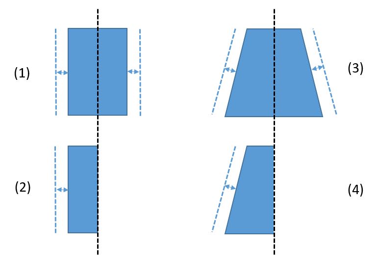
See the below. Each of these shows uniform offset normal to the true profile. The section line between 1 and 2 (as well as 3 and 4) shows that if you consider the uniform offset of half of a width shaped FOS it is the same as the uniform offset of a planar feature. The same is true of a tapered feature.

uniform_offset_2_v9uf1z.jpg


As far as showing this unlimited uniform offset which prevents a conical feature being contained by/containing a conical boundary one could utilize an expanding clamp such as machined into an "external" conical shape to mate with a similar "internal" conical feature on a sample part. The clamp can be infinitely expanded and will never reach a point where it is captured by the mating part. This "expansion" is the same as the aforementioned uniform offset.
 
chez311,
Considering that there is no unique size dimension to a conical feature, and therefore I hope we agree that a rigid, non-adjustable conical simulator can always be used for conical UAME simulation, and it is by the way, probably the only possible full-extent simulator for a complete "apexed", non-truncated cone (most chances that it would be impossible to use the "modified" expanding clamp per your link as it will not close until zero at the small end and will not cover the end near the apex*). Using a rigid simulator, the only way to achieve the effect of "uniform normal offset towards the material" which you show in your latest graphic would be moving the envelope cone axially towards the considered cone (or vice-versa). Saying that there is no limit to such offset is exactly like saying that there is no limit to a translation of a planar datum feature simulator towards the material of a planar datum feature. As for "containment", the standard doesn't define "contain", so we need to rely purely on our English and decide if a cone that is seated inside another cone is contained by it or not.

*Edit: by the same principle it cannot expand infinitely or even a bit within an internal considered come as it will uncover the end near the apex.
 
chez311
(need to start new thread - enough for me being posted for this thread regarding tangents..yes myself included)

Mix and match can always add undue complexity to problems. (i.e. 1994 does not include FOS type irregular..can cite other definitions and defaults that have changed or have been added over the years from ANSI Y14.5M 1973 thru ASME Y14.5 2018, not to mention any company's particular amendments which can typically be found in a company's "drawing interpretation" document(s) ) Lets stick to the standard referenced in this thread (2009)

chez311 said:
Tolerance zones are always held in basic relationship to the theoretical datums, and their behavior is dictated by the type of tolerance zone (ie: Orientation tolerance dictates orientation is held but not location, Position tolerance dictates both location and orientation are held).

Tolerance zones are not "..held in basic relationship to the theoretical datums,...". Tolerance zones are located and oriented to a DRF which is defined by Datum Simulators (theoretical or physical) which as closely as possible using "gage accuracy" establish "theoretical datums in the physical world" via physical gage tools (not going to introduce new technology vs. attribute gages at this time). One can not physically touch a theoretical axis or plane which is a fundamental principle of GDT governed by ANSI thru ASME Y14.5 standards.

chez311 (to Burunduk) said:
See the below. Each of these shows uniform offset normal to the true profile. The section line between 1 and 2 (as well as 3 and 4) shows that if you consider the uniform offset of half of a width shaped FOS it is the same as the uniform offset of a planar feature. The same is true of a tapered feature.

Tolerance zones are centered about axis and center planes or uniformly distributed about the true geometric form. Boundaries and envelopes are not tolerance zones.

Your sketches (in planar graphic space) appear to be equating an offset planar surface in a single "normal" vector, and the same for a cylindrical or conical surface. Cylindrical and conical surfaces have normal vectors in 360 degrees about an axis. With that in view the cylindrical surface is far more similar to a conical surface. Where I see nothing in themselves (cylindrical and conical surfaces) having similarities to a planar surface.

I have know idea what you believe about threaded holes including their conical surface countersinks being located with tolerance of location controls for FOS(s). Screw threads by definition have a rigid helical structure wrapped around a cylindrical or conical surface. Now what ? regarding an AME especially when the tolerance of location is measured relative to the "imaginary" simulated pitch cylinder.

2.9 SCREW THREADS said:
Each tolerance of orientation or position and datum
reference specified for a screw thread applies to the axis
of the thread derived from the pitch cylinder. Where an
exception to this practice is necessary, the specific feature
of the screw thread (such as “MAJOR DIA” or “MINOR
DIA”) shall be stated beneath the feature control frame,
or beneath or adjacent to the datum feature symbol, as
applicable. See Fig. 7-35.


Considering that there is no unique size dimension to a conical feature, and therefore I hope we agree that a rigid, non-adjustable conical simulator can always be used for conical UAME simulation

Skipping over whether a UAME exists, yes I've already said several times that a fixed conical simulator could be used in place of an "expanding" one - thats not to say an "expanding" one (or one with uniform offset) is not possible.

and it is by the way, probably the only possible full-extent simulator for a complete "apexed", non-truncated cone

Sure - other than digital/virtual simulation, however a non-truncated cone would be a poor primary datum feature - otherwise depending on the form deviation of the feature contact could be dictated by this vertex/apex.

Saying that there is no limit to such offset is exactly like saying that there is no limit to a translation of a planar datum feature simulator towards the material of a planar considered feature. As for "containment", the standard doesn't define "contain", so we need to rely purely on our English and decide if a cone that is seated inside another cone is contained by it or not.

Exactly, hence the aforementioned similarities between a planar and conical/tapered feature. A conical/tapered simulator cannot contain a conical/tapered feature just as a planar simulator cannot contain a planar feature.

Personally that should be enough to say a conical feature and conical envelope is not a FOS, however I think no matter which way you cut it you arrive at the same answer. In order for a feature to "contain or be contained by" a UAME, would you not agree such a UAME must exist first? An AME is defined as "a similar perfect feature(s) counterpart of smallest size that can be contracted about an external feature(s) or largest size that can be expanded within an internal feature(s)" - a literal interpretation could say that since size is not defined for a conical feature, such an envelope does not exist OR a more general interpretation could say that there is no limit to the uniform offset therefore such an envelope does not exist OR since there is no limit to the uniform offset the envelope is one of "unlimited offset" which I do not think is much more useful than saying it does not exist. Pick your poison.
 
Mix and match can always add undue complexity to problems

ASME Y14.5.1 is the mathematical basis for Y14.5 - in many cases Y14.5 either does not provide an explanation for, or a sufficient explanation/definition for, concepts which can be unambiguously mathematically expressed per Y14.5.1 for example the concept of size. Y14.5-2009 itself does not provide a sufficient, unambiguous definition for size. Indeed its right there quite literally in the beginning of Y14.5-2009, this is not "mix and match":

ASME Y14.5-2009 said:
1.1 SCOPE
This Standard establishes uniform practices for stating and interpreting dimensioning, tolerancing, and related requirements for use on engineering drawings and in related documents. For a mathematical explanation of many of the principles in this Standard, see ASME Y14.5.1. Practices unique to architectural and civil engineering and welding symbology are not included.

If you are referencing my inclusion of the 2018 version of the definition for the [BSC] modifier, it is only because of the unfortunate inclusion of the term "location" in the 2009 definition. Regardless, inclusion of this or not does not change my assertion about what the [BSC] modifier does. It is not required to imply basic location of tolerance zones to the DRF (this is dictated by the type of tolerance zone specified) or simulators to each other, the latter being one of the fundamental requirements of datum feature simulators for 2009 and beyond:

ASME Y14.5-2009 said:
4.5.2 Requirements
Datum feature simulators shall have the following
requirements:
(a) perfect form.
(b) basic orientation relative to one another for all the datum references in a feature control frame.
(c) basic location relative to other datum feature simulators for all the datum references in a feature control frame, unless a translation modifier or movable datum target symbol is specified. See Figs. 4-9, 4-19, and 4-32, illustration (a).

(d) movable location when the translation modifier or the movable datum target symbol is specified. See Figs. 4-19, 4-32, illustration (b), and 4-49.
(e) fixed at the designated size, when MMB or LMB is specified.
(f) adjustable in size, when the datum feature applies at RMB.

Your sketches (in planar graphic space) appear to be equating an offset planar surface in a single "normal" vector, and the same for a cylindrical or conical surface. Cylindrical and conical surfaces have normal vectors in 360 degrees about an axis. With that in view the cylindrical surface is far more similar to a conical surface. Where I see nothing in themselves (cylindrical and conical surfaces) having similarities to a planar surface.

The sketches can be extruded normal to the surface shown (in and out of the screen/page) to represent a planar tapered feature or revolved around an axis to represent a cone. My statements are no less valid.
 
chez311

As always I am interested in and appreciative of others interpretations and view points. Even if it comes down to, we agree to disagree.

That is not to say I disagree with all you have posted.

Thank for your time to reply

 
chez311 said:
a literal interpretation could say that since size is not defined for a conical feature, such an envelope does not exist

There is no unique size dimension, but possibly there are "actual local sizes". The actual local size definition (1.3.54 in 2009) is:
"the measured value of any individual distance at any cross section of a feature of size" the bolded part introduces the chicken and the egg dilemma but it doesn't rule out the cone from the definition.

Before we can say that a UAME envelope does not exist, we should attempt at creating one, and see if it misbehaves by, for example, offsetting infinitely as you say. I will make one more attempt at explaining my issue with "unlimited offset":
Consider a truncated cone with a base diameter of 50mm and on opposite face diameter of 35mm. A theoretical digitally simulated "candidate" UAME envelope starts offset in the direction normal to the true profile at uniform (neglecting feature's form error effect) distance of 5mm from the considered conical surface (similar to fig. (3) in your last posted image), then with the offset the distance reduces to 4mm, 3mm, 2mm, 1mm reaching at some point in time 0mm, touching on the conical feature surface at some high points. The envelope attempts to continue it's "unlimited" offset towards the material, but the normal distance does not reach a negative value (which would result of penetration of the envelope into the material), and just keeps remaining at the zero normal distance that was already achieved at a previous point in time. Doesn't seem like unlimited offset happens (with any kind of feature by the way). This could be demonstrated with the conical version of the expanding clamp you referred to.
 
There is no unique size dimension, but possibly there are "actual local sizes". The actual local size definition (1.3.54 in 2009) is:
"the measured value of any individual distance at any cross section of a feature of size"

Another example of the ambiguous definitions of size in Y14.5 - it tells you nothing about how these cross sections should be taken. Side note - the draft for Y14.5.1-20xx includes definitions for "actual local size" however it is meant as an approximation of size and they do not supercede the swept spheres definition of size.

Regardless in the context of cones and the definition of the AME "a similar perfect feature(s) counterpart of smallest size that can be contracted about an external feature(s) or largest size that can be expanded within an internal feature(s)" there would be no one maximum or minimum - an "actual local size" of any value could be had depending on where you take the cross section. I don't see how this helps your case.

A theoretical digitally simulated "candidate" UAME envelope starts offset in the direction normal to the true profile at uniform (neglecting feature's form error effect) distance of 5mm from the considered conical surface (similar to fig. (3) in your last posted image), then with the offset the distance reduces to 4mm, 3mm, 2mm, 1mm reaching at some point in time 0mm, touching on the conical feature surface at some high points. The envelope attempts to continue it's "unlimited" offset towards the material, but the normal distance does not reach a negative value (which would result of penetration of the envelope into the material), and just keeps remaining at the zero normal distance that was already achieved at a previous point in time.

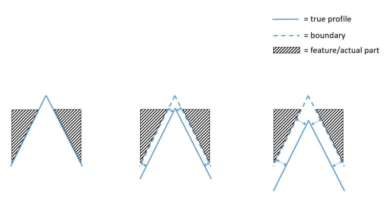
Thats a confusing convention by which to define "offset" - *all you're saying is that it can be at 5mm, 4mm, 3mm, 2mm, 1mm, or 0mm (true profile/envelope are coincident) however it can also be 6mm, 7mm, 8mm, 100mm, and any value to infinity. See my below progession very similar to what I showed in my earlier powerpoint, taken from left to right - the boundary starts at 0 offset from the true profile (true profile and boundary/envelope are coincident), and can increase infinitely *while maintaining contact between the envelope and the feature no matter the offset. This would be the same result if a part was mated to the expansion clamp (machined into an external conical profile mated with an internal conical feature) I referred to - if it was "expanded" as the clamping screw was tightened it would just continue to push the part away and it would never "clamp" or be contained by the mating conical feature.

limited_expansion_zvytsc.jpg


*Edited for clarity
 
chez311, for the record I'm not promoting the position that a conical feature is a FOS, I'm just questioning some of the arguments why it isn't.

chez311 said:
there would be no one maximum or minimum - an "actual local size" of any value could be had depending on where you take the cross section. I don't see how this helps your case.

The purpose is just to relate the "size" term to a conical feature for the sake of the literal interpretation you brought up. Since as you mentioned size has somewhat ambiguous definition it is not impossible to suggest that a cone has (local) size.

I am confused about your graphic showing 3 participants of a simulation process: true profile, boundary and feature/actual part. I always imagine 2 participants: boundary (envelope simulator) and the actual feature.
ASME Y14.5 2009 defines "true profile" in para. 8.2:
"A true profile is a profile defined by basic radii, basic angular dimensions, basic coordinate dimensions, basic size
dimensions, undimensioned drawings, formulas, or mathematical data, including design models".

True profile is a theoretical part of the product definition and should be on the drawing or CAD model, not in the simulation process moving where it wants to, separate from the part and the simulator. What it should do is only set the included angle of the simulator (envelope) and if you insist dictate the "normal direction" of relative movement between part and simulator prior to contact. Therefore I don't really know how to treat the offset between the envelope and the true profile while the envelope is kept adjacent to the part all the time, what conclusions can be drawn from it?

As for the part getting pushed away from the conical expansion clamp: this would be a result of the part slipping away axially. As I mentioned - since a proper potential UAME simulator should cover the entire length of the considered feature, if it is impossible to prevent such slippage, an expanding clamp shouldn't be used. If you mate a fixed conical simulator into the feature, no such problem occurs.
 
The purpose is just to relate the "size" term to a conical feature for the sake of the literal interpretation you brought up. Since as you mentioned size has somewhat ambiguous definition it is not impossible to suggest that a cone has (local) size.

I just don't see where this gets you as it doesn't make sense in the context of the UAME definition, but I don't imagine its worth belaboring the point.

I am confused about your graphic showing 3 participants of a simulation process: true profile, boundary and feature/actual part. I always imagine 2 participants: boundary (envelope simulator) and the actual feature.

https://www.eng-tips.com/viewthread.cfm?qid=448819)[/URL]]Using these definitions, the conical feature (with or without the flat surface at the tip) is certainly not a feature of size. If you imagine the true profile starts out roughly aligned with the actual feature and an offset envelope progresses toward the material, it never reaches a point where it can't progress further. The feature just gets pushed away from the true profile.

I'm not sure where your confusion is. This has quite literally been in the discussion since I first introduced the referenced thread. The uniform offset that has been discussed is the normal distance between the true profile and an envelope which contacts the feature. I have mentioned this concept repeatedly. Yes the true profile is a theoretical reference for the uniform offset of the envelope of interest - we discuss the connection between theoretical and physical all the time - physical/theoretical datum feature simulators, theoretical datums, datum reference frame (three theoretical mutually orthogonal planes), virtual condition, etc.. I'm not sure why this particular theoretical boundary could not be discussed in the same context.

For an RMB datum feature the simulator moves normal to the true profile uniformly offset a measurable distance from the true profile as in 4-31(a)

For a datum feature denoted [BSC] the simulator is coincident with the true profile as in 4-31(b)

I don't see an issue here discussing true profile in relation to the simulation process.

As I mentioned - since a proper potential UAME simulator should cover the entire length of the considered feature

It could and would, except for conical/tapered features which have a small end that is very near to coming to a point.

if it is impossible to prevent such slippage, an expanding clamp shouldn't be used.

Thats just a result of the geometry. "Expansion without slippage" is not a requirement found anywhere in the standard.

If you mate a fixed conical simulator into the feature, no such problem occurs.

Same could be said for a planar feature. Would you say then that a planar feature is a FOS?
 
chez311 said:
I'm not sure why this particular theoretical boundary could not be discussed in the same context.

I am not against discussing theoretical boundaries, but I honestly think that "true profile" is not even a boundary. There are inner boundary, outer boundary, maximum material boundary, least material boundary, but not "true profile boundary". This term was used in a questionable way and overused in the context of UAME in both discussions.
True profile is really not part of the UAME definition or its simulation process.
Consider a cylindrical feature of specified diameter 90+/-0.5. What is the true profile? Requoting para. 8.2: "A true profile is a profile defined by basic radii, basic angular dimensions, basic coordinate dimensions, basic size
dimensions, undimensioned drawings, formulas, or mathematical data, including design models". Since no basic dimensions or anything of the above involved, "true profile" is irrelevant. If it is still necessary to set a boundary as an origin of "uniform offset" of the UAME simulator (though no such thing is mentioned in the definition) then the most sensible choice for this would be the MMB boundary. Notice how the "Means this" description in fig. 4-31(a) that you brought up mentions progression "normal from the MMB", there is no mention of "true profile". Even though this example is in the context of a planar datum feature simulator, this concept can conveniently be translated to the case of a cylindrical feature of size UAME simulation, I suppose no explanation is needed. Obviously, a contraction of an external cylindrical UAME simulator can begin from an envelope larger than the MMB, but whatever happens beyond the MMB envelope, be it uniform offset, non-uniform offset, limited or unlimited, is irrelevant to the process.

On the grounds of this, the MMB boundary can be the "offset origin" for progression of a conical envelope simulator if such origin is necessary. The standard doesn't explicitly define an MMB boundary of a conical shape, but it does lay a solid enough foundation for it; One of the recommended ways to dimension a conical taper is 2.13(c) : "a toleranced diameter at both ends of a taper and a toleranced length. See Fig. 2-19, illustration (a)."
The referenced figure shows a taper dimensioned Dia. 30+/-0.05 at the base and Dia. 20+/-0.05 at the smaller end. Para. 2.13 also defines: "Conical taper is the ratio of the difference in the diameters of two sections (perpendicular to the axis) of a cone to the distance between these sections. Thus, taper = (D - d ) / L. " Naturally, the MMB boundary should have the same "taper" value and cross section of diameter 30.05 adjusted around the base and a cross section of diameter 20.05 adjusted around the smaller end and there is your boundary from which "uniform offset in normal direction" can originate, without dealing with infinite/unlimited offsets.
 
I am not against discussing theoretical boundaries, but I honestly think that "true profile" is not even a boundary. There are inner boundary, outer boundary, maximum material boundary, least material boundary, but not "true profile boundary".

We could argue semantics all day, I don't think thats a fruitful endeavor. Call it whatever you wish - theoretical feature, shape, profile, etc...

This term was used in a questionable way and overused in the context of UAME in both discussions.

I would have to strongly disagree. I think your use of MMB of a conical feature considered by itself is far more questionable - more on both below.

Notice how the "Means this" description in fig. 4-31(a) that you brought up mentions progression "normal from the MMB", there is no mention of "true profile".

You must have missed the reference to 4-31(a) (as well as 4-29(a) and 4-30(a)) in the body of the standard. See below, it absolutely mentions progression normal to the true profile during simulation.

ASME Y14.5-2009 section 4.11.4 said:
(g) Secondary and Tertiary Surface RMB. Where the datum feature (secondary or tertiary) is a surface, RMB applied to the datum feature requires the datum feature simulator to expand, contract, or progress normal to the true profile of the feature from its MMB to its LMB until the datum feature simulator makes maximum possible contact with the extremities of the datum feature while respecting the higher precedence datum(s). See Figs. 4-29, illustration (a); 4-30, illustration (a); and 4-31, illustration (a).

Coincidentally, as I pointed out before, Y14.5-2018 updates the definition for the [BSC] modifier to also include a more general reference to the true profile in conjunction with fig 7-35 which is the same as Y14.5-2009 fig 4-31(c). This is again in relation to simulation.

ASME Y14.5-2018 section 7.11.10 said:
To indicate that the true geometric counterpart is defined by the basic dimensions of the true profile of the datum feature, the term “[BSC],” meaning basic, shall follow the datum reference letter in the feature control frame. See Figure 7-35.

The standard doesn't explicitly define an MMB boundary of a conical shape, but it does lay a solid enough foundation for it

No - considered by itself a conical feature does not have an MMB. It would only have an MMB if it had location constraint to a higher precedence datum feature. Discussing the MMB of a conical primary datum feature is just as flawed as discussing the MMB of a planar primary datum feature.
 
pylfrm,

Is there any chance you could help me answer the below question as it relates to your generalized definition of the UAME and uniform offset from the true profile (namely the UAME defined as: " A theoretical envelope outside the material, uniformly offset from a feature's true profile as far as possible in the direction toward the material")? I don't mean to drag you into this but I simply don't have what I think is a satisfactory answer.

Consider a cylindrical feature of specified diameter 90+/-0.5. What is the true profile?

Perhaps we could even expand the question to "does a feature, or collection of features, defined with non-basic (directly toleranced or +/- dimensions) have a true profile?"

*side note to Burunduk - I was under the impression that we were discussing a conical/tapered feature defined with a basic angle. Regardless of the answer to the above question I don't think it has any impact on consideration of uniform offset normal to the true profile of a conical/tapered feature defined with a basic angle (or any other feature defined with basic dimensions). If you want to consider a feature defined with directly toleranced/non-basic dimension(s) I don't mean to pass the buck but I don't have a satisfactory answer for you.
 
chez311, I admit that I missed the reference to "true profile" in para. 4.11.4, but reading this paragraph please notice that as I said earlier in my post from 19 Nov 19 04:36 ("...dictate the "normal direction" of relative movement between part and simulator prior to contact") it only sets the direction of "progression":

4.11.4 (g)
"...expand, contract, or progress normal to the true profile of the feature from its MMB to its LMB until the datum feature simulator makes maximum possible contact... "

Since true profile only directs an offset, the distances from it are irrelevant during simulation, and as I've been trying to explain, "unlimited offset" from true profile doesn't really tell anything about the feature. The only offset that may be meaningful as a distance is offset from the MMB (as para 4.11.4 confirms by the bolded section of the quote above). When the datum feature simulator makes "maximum possible contact" (quoting the standard) with the feature it will not be at an infinite offset from the MMB.

The MMB of a conical primary datum feature has a solid ground to be defined, and not half "as flawed as discussing the MMB of a planar primary datum feature."

"1.3.4 Boundary, Maximum Material (MMB)
boundary, maximum material (MMB): the limit defined by a tolerance or combination of tolerances that exists on or outside the material of a feature(s)."

The above-mentioned limit can be a derivative of size specification, or range of local sizes along a length:

2.13 Conical Tapers:
"A conical taper may also be specified by one of the following methods:
(a) a basic taper and a basic diameter (see Fig. 2-21).
(b) a size tolerance combined with a profile of a surface tolerance applied to the taper (see para. 8.4.2).
(c) a toleranced diameter at both ends of a taper and a toleranced length. See Fig. 2-19, illustration (a)."

Regardless, a defined MMB can also be satisfied by a feature specified with only basic dimensions and profile tolerance, easily applicable for a conical feature.
 
True profile is really not part of the UAME definition or its simulation process.

For reference:
ASME Y14.5-2009 para. 1.3.25.1 said:
unrelated actual mating envelope: a similar perfect feature(s) counterpart expanded within an internal feature(s) or contracted about an external feature(s), and not constrained to any datum(s).

"A theoretical envelope with a uniform normal offset from a feature's true profile" is my attempt to provide a less ambiguous replacement for "similar perfect feature(s) counterpart", which is not properly defined.

"Outside the material" and "offset as far as possible in the direction toward the material" is my attempt to provide a less ambiguous replacement for "expanded within an internal feature(s) or contracted about an external feature(s)", the meaning of which is only obvious for simple features such as cylinders, spheres, or widths between parallel planes.


Consider a cylindrical feature of specified diameter 90+/-0.5. What is the true profile?

If we take ASME Y14.5-2009 at its word, the true profile is undefined for such a feature. This is something I did not address in thread1103-448819.

I think it is useful in certain circumstances (this being one of them) to think of the true profile as being a cylinder of unspecified diameter. ISO 1101:2017 takes this approach in allowing the application of profile tolerances to such features, although only with the OZ modifier (analogous to the dynamic profile modifier of ASME Y14.5-2018).

Perhaps I shouldn't use the term "true profile" for this, but I was hoping to avoid inventing new terms.


Perhaps we could even expand the question to "does a feature, or collection of features, defined with non-basic (directly toleranced or +/- dimensions) have a true profile?"

The concept of "cylinder of unspecified diameter" could be extended to other features or collections of features. The implications of the unspecified aspect(s) of the geometry would need to be considered for each case though.


pylfrm
 
]I think it is useful in certain circumstances (this being one of them) to think of the true profile as being a cylinder of unspecified diameter.[/b] ISO 1101:2017 takes this approach in allowing the application of profile tolerances to such features, although only with the OZ modifier (analogous to the dynamic profile modifier of ASME Y14.5-2018).

Perhaps I shouldn't use the term "true profile" for this, but I was hoping to avoid inventing new terms.

This is kind of along the lines of what I was thinking, I am in full agreement. I have no issue with this or with using the term "true profile" - I see no need to invent a new term, and I think it fits well within the construct of the existing Y14.5 standard/definitions as well as can be used to address cases which are not directly covered by the text/figures in the standard.

Contrary to some of the assertions above, I think that MMB/LMB can be explained in terms of the true profile and not the other way around or MMB/LMB being an independent "boundary" in its own right. Could we not define MMB as the offset from the true profile, within the feature's tolerance zone, which results in the maximum material or something similar? This is why without location constraint for a conical/tapered or planar feature MMB does not make sense as the amount and direction of offset from the true profile which results in the maximum material is undefined.

Also as far as "unspecified" would you say that the true profile could be anything between the applicable toleranced dimension? Ie: if there is a cylindrical feature of 30+/-0.5 the diameter of the true profile could be anything between 29.5 and 30.5 ?
 
but reading this paragraph please notice that as I said earlier in my post from 19 Nov 19 04:36 ("...dictate the "normal direction" of relative movement between part and simulator prior to contact") it only sets the direction of "progression":

I would say instead that MMB "only" sets a limit (direction and amount) to the amount the simulator may be offset from the true profile which results in the Maximum Material within the feature's tolerance zone. This is supported by the text. It doesn't prevent discussion of MMB as a part of the simulation process the same as it doesn't for the true profile - I'm not sure why you are so quick to dismiss true profile for similar reasons.

ASME Y14.5-2009 said:
"1.3.4 Boundary, Maximum Material (MMB)
boundary, maximum material (MMB): the limit defined by a tolerance or combination of tolerances that exists on or outside the material of a feature(s)."

Since true profile only directs an offset, the distances from it are irrelevant during simulation, and as I've been trying to explain, "unlimited offset" from true profile doesn't really tell anything about the feature. The only offset that may be meaningful as a distance is offset from the MMB (as para 4.11.4 confirms by the bolded section of the quote above). When the datum feature simulator makes "maximum possible contact" (quoting the standard) with the feature it will not be at an infinite offset from the MMB.

Maximum possible contact is a can of worms that I don't think is worth opening. Its referenced many times in the standard and I think may be one of the most poorly, ambiguously, and frustratingly defined terms in the whole standard. I think its best mostly to ignore it and instead focus on the behavior of a UAME (or potential UAME) which can be defined in concrete terms - maximum expansion/contraction/offset of the envelope.

Lets strip this down for a second and get back to the requirement per the standard for a FOS to "contain or be contained by" an actual mating envelope. Imagine a conical feature controlled by RMB/RFS set on either a conical "expanding" simulator (expanding clamp) or a fixed conical simulator. The "expanding" simulator can be "expanded" (or offset) through its entire range and never reach a point where it has contained or been contained by the feature - you can always simply pull it off the simulator (as opposed to a cylindrical expanding clamp that will reach a point where further expansion/contraction/offset is not possible and will contain/be contained by the clamp so it cannot be removed). The same is obviously true of a fixed simulator - if you set a part with a conical feature on it you can also simply just remove it (we already agreed a fixed simulator is valid for a conical feature at RMB/RFS - there is no analog as a fixed cylindrical simulator is not valid for a cylindrical feature specified at RMB/RFS). If this behavior satisfies your definition of containment then you must also say a single planar feature is also a FOS. I don't see how you could say otherwise.

The above-mentioned limit can be a derivative of size specification, or range of local sizes along a length:

2.13 Conical Tapers:
"A conical taper may also be specified by one of the following methods:
(a) a basic taper and a basic diameter (see Fig. 2-21).
(b) a size tolerance combined with a profile of a surface tolerance applied to the taper (see para. 8.4.2).
(c) a toleranced diameter at both ends of a taper and a toleranced length. See Fig. 2-19, illustration (a)."

Regardless, a defined MMB can also be satisfied by a feature specified with only basic dimensions and profile tolerance, easily applicable for a conical feature.

(a) Fig 2-21 includes location of the taper to the perpendicular flat faces.
(b) para 8.4.2 includes reference to fig 8-17 and fig 8-18 (two very controversial figures in 2009 by the way). Fig 8-17 includes location to the large perpendicular flat face (dia30+/-0.2 located at 0 to the flat face) and fig 8-18 includes location to the small perpendicular flat face.
(c) Fig 2-19 includes location of the the taper to the perpendicular flat faces

"Size" of a conical/tapered feature only matters in relation to something else - often the perpendicular flat faces adjacent to it. A conical/tapered feature is fully defined by included angle alone. If, as when it is referenced as a primary datum feature, the conical/tapered feature is considered by itself and not in relation to any other feature (no location constraint) then there is no MMB.
 
chez311 said:
I would say instead that MMB "only" sets a limit (direction and amount) to the amount the simulator may be offset from the true profile which results in the Maximum Material within the feature's tolerance zone. This is supported by the text. It doesn't prevent discussion of MMB as a part of the simulation process the same as it doesn't for the true profile - I'm not sure why you are so quick to dismiss true profile for similar reasons.

Ignoring the fact that it isn't defined even for simple features of size specified without basic dimensions, the reasons why I suggest to replace your use of "true profile" in the context of UAME simulation with an MMC/MMB boundary are:
a. True profile is not a boundary and has no defined location in space relative to part, simulator, etc.
b. MMB/MMC boundary as an origin of simulator progression (assuming such origin is necessary) never results in an unlimited amount of offset from the origin during a simulation. If I'm not mistaken, the unlimited offset is what you find to be the failing factor in UAME simulation for a conical feature. As far as I'm concerned, the amount (and at some cases direction - I will address this below) of offset doesn't affect anything and shouldn't even be considered; if the true profile of an external, +/- toleranced cylinder is a cylinder of unspecified diameter as you and pylfrm suggest, then this diameter can as well be infinite and so is the amount of contraction/offset from true profile during simulation. Does the process fail? No, because it doesn't matter. As for direction - the direction of offset/contraction for a cylinder should be radial (relative to the simulator axis). The direction of progression of a conical simulator can be radial (contracting clamp) or axial (fixed simulator) and in both of these cases, it effectively would be in a normal direction to the theoretical conical surfaces. There are probably some nuances that I don't consider here but I don't think there is a purpose in analyzing all this - the simulation process has little room for failure.

chez311 said:
The same is obviously true of a fixed simulator - if you set a part with a conical feature on it you can also simply just remove it

... Or, you can simply just keep it in place. The only reasonable justification for "simulation impossible" would be an inability to "set a part with a conical feature on it" in the first place. As long as it's set, it contains/being contained.

chez311 said:
If this behavior satisfies your definition of containment then you must also say a single planar feature is also a FOS. I don't see how you could say otherwise.

A planar feature can not surround or be surrounded by a counterpart with opposed points, and can not have size dimensions associated with it.
 
a. True profile is not a boundary and has no defined location in space relative to part, simulator, etc.

It absolutely does.

ASME Y14.5-2009 said:
8.2 PROFILE
A profile is an outline of a surface, a shape made up of one or more features, or a two dimensional element of one or more features. Profile tolerances are used to define a tolerance zone to control form or combinations of size, form, orientation, and location of a feature(s) relative to a true profile.

ASME Y14.5-2009 said:
8.3.1 Uniform Tolerance Zone
A uniform tolerance zone is the distance between two boundaries equally or unequally disposed about the true profile or entirely disposed on one side of the true profile. Profile tolerances apply normal (perpendicular) to the true profile at all points along the profile. The boundaries of the tolerance zone follow the geometric shape of the true profile.

If a profile tolerance controls "form or combinations of size, form, orientation, and location of a feature(s) relative to a true profile" then the true profile must be constrained in location/orientation relative to the DRF.

MMB/MMC boundary as an origin of simulator progression (assuming such origin is necessary) never results in an unlimited amount of offset from the origin during a simulation.

MMB/MMC boundary is just one end of the limit of possible offset from the true profile. Sometimes that limit does not exist - as is the case with a conical/tapered or planar primary datum feature. As I mentioned already there is no MMB/MMC limit of a conical/tapered feature which is not location constrained.

if the true profile of an external, +/- toleranced cylinder is a cylinder of unspecified diameter as you and pylfrm suggest, then this diameter can as well be infinite and so is the amount of contraction/offset from true profile during simulation.

I wouldn't say unspecified = infinite. If the diameter of a cylindrical feature is toleranced 30+/-0.5 the way I would interpret it is that the diameter of the true profile can be anything between 29.5 and 30.5 and the amount of offset from the true profile anything between 0 and 0.5, noting of course that the feature must still fall within the stated tolerance.

... Or, you can simply just keep it in place. The only reasonable justification for "simulation impossible" would be an inability to "set a part with a conical feature on it" in the first place. As long as it's set, it contains/being contained.

Thats not what I said. I did not say it is impossible to simulate - I said that the feature does not contain or is contained by the simulator. Obviously a fixed conical simulator does the job of primary datum feature simulation just fine - however it is not a FOS and is not simulating the UAME.

If your definition of containment is "as long as it's set, it contains/being contained" what features do you imagine don't satisfy that - besides a single planar feature (due to your aforementioned not associated with a size dimension)? Is everything except a planar feature a FOS? I'm hard pressed to think of a shape that wouldn't satisfy that. Not to mention the fact that I obviously don't agree with your definition of containment.
 
Also as far as "unspecified" would you say that the true profile could be anything between the applicable toleranced dimension? Ie: if there is a cylindrical feature of 30+/-0.5 the diameter of the true profile could be anything between 29.5 and 30.5 ?

I think it's best to leave it as completely unspecified. Do you see some potential benefit in what you propose though?


pylfrm
 
Status
Not open for further replies.

Part and Inventory Search

Sponsor