Continue to Site

Eng-Tips is the largest engineering community on the Internet

Intelligent Work Forums for Engineering Professionals

  • Congratulations KootK on being selected by the Eng-Tips community for having the most helpful posts in the forums last week. Way to Go!

Orientation of a center plane of a tapered feature 2

Status
Not open for further replies.

Burunduk

Mechanical
May 2, 2019
2,354
A designer applied perpendicularity feature control frame with the leader pointing to a centerline representing the center plane of an internal taper feature (a "pocket" with symmetrical non-parallel opposed surfaces). I don't consider this specification valid according to ASME Y14.5-2009 but I'm struggling to provide a good explanation of why perpendicularity shouldn't be used this way. The one use of perpendicularity I know when it is applied on a virtual, derived geometry (as opposed to an actual surface) is when a center plane/axis of a feature of size is controlled. It doesn't seem right in the context of a tapered feature, not associated with a size dimension - but I can't form a good argument why. A valid point is that a center plane can be derived from a tapered feature (for example, a datum plane derived from tapered datum feature), and I suppose that a way to evaluate the derived plane orientation relative to a DRF can be found. I need your help, please.
 
Replies continue below

Recommended for you

chez311 said:
A conical/tapered boundary expanded/contracted against (or uniformly offset toward) a conical/tapered feature unconstrained to any DRF will allow infinite expansion/contraction (uniform offset).

chez311, regarding "infinite expansion/contraction" - help me to understand this concept, please. For starters, pylfrm mentioned in the post you linked to that a cone is defined by the included angle alone. Similarly, you mentioned in this post a couple of times that cones have no size. I agree with both statements, but only if the assumption that a conical UAME envelope must have an apex and an infinite length is adopted (not that I understand why it is so, but we can discuss this after the current point is clarified). So the question is - how can something sizeless be expanded or contracted in the first place, let alone infinitely? Maybe the clarification of "uniform offset" in parenthesis is the key? Uniform offset in what direction? Axial? (Radial uniform means size adjustment, doesn't it? Size that doesn't exist...).
 
Burunduk

Maybe attached sketch can be conversation starter (at least a graphic start)

Not fully dimensioned hopefully captures OP topic

Plenty to discuss
Composite Profile of Surface:
upper frame for size,location and orientation
lower frame to tighten perpendicularity

Graphics display in profile DRF imply by fundamental rules (1.4 (k))that the center plane of tapered slot are coincident (basic 0 distance) to Datum Feature A axis
 
 https://files.engineering.com/getfile.aspx?folder=1d5361be-7bb4-4d24-862f-14da117a1ae0&file=dtm.GDT.WedgePerpCntrl_111419.JPG
So the question is - how can something sizeless be expanded or contracted in the first place, let alone infinitely? Maybe the clarification of "uniform offset" in parenthesis is the key?

Shapes other than these (tapered or not) will not have a unique actual value for size. The concept of "uniform offset from the true profile" expands (ha!) the concept of "expansion/contraction" to features/shapes of all types.

Forgive me for quoting myself but the juxtaposition of these two should answer your question.

Uniform offset in what direction?

Normal to the true profile
 
dtmbiz,

Side note - I have no issue with profile applied to a conical/tapered surface. This is actually the preferred method and does not require the feature/collection of features be a FOS. The OP asked about applying an orientation control (perpendicularity) control the center plane (recently described "bisecting plane") hence the discussion about FOS and UAME.
 
pylfrm,

If I'm to play devil's advocate for a bit, what do you think is the biggest hurdle (or alternately, a solution) to directly controlling the orientation or position of the derived axis/centerplane of a cone/taper similar to RFS orientation or position for a FOS? Of course as you can tell I'm firmly on the side that, not being a FOS and lacking a UAME a conical/tapered feature cannot be controlled with orientation and position as written in the standard. The fact remains that intuition tells us we should be able to derive an axis/centerplane from a conical/tapered feature and we should be able to control the orientation and position of said axis/centerplane - perhaps through a method which resembles simulation of a primary datum feature? I think its this disconnect (a cone establishes an axis - why can't I control it with position/orientation?) that is probably this biggest sticking point for people.
 
The orientation tolerance refers to two planner datum features which are part of the DRF of the part. There is a separate drawing that defines the form and angle of the taper by the means of a profile control but it doesn't orient or locate the tapered feature with reference to anything.

What are the perpendicularity and profile tolerance values? I am mainly interested in the ratio between them, but it might be helpful to have specific numbers for discussion.

The perpendicularity tolerance isn't specified as MMC or LMC, is it?

Is the "TAPER BISECTING PLANE" nominally perpendicular to both datum features?

The perpendicularity tolerance controls two rotational degrees of freedom. How does the drawing control other three (one rotational and two translational) meaningful degrees of freedom of the taper feature?

Did you consider controlling the orientation of the two flat surfaces of the taper individually? That could be done with angularity or the lower segment(s) of composite profile.


So the question is - how can something sizeless be expanded or contracted in the first place, let alone infinitely? Maybe the clarification of "uniform offset" in parenthesis is the key? Uniform offset in what direction? Axial? (Radial uniform means size adjustment, doesn't it? Size that doesn't exist...).

I think it's best to avoid the expansion/contraction terminology. To me it implies a change in geometry, but a surface with a uniform offset* from a cone is just an identical cone. Same with a plane.

*Yes, I did (and do) mean normal to the true profile.

The notion of expansion/contraction also breaks down for features which are aren't purely external or purely internal, such as the interlocking profiles on the ends of this floor mat segment:

6892t32p3-g01c-digital@1x_637026327236778280.png


chez311,

I don't see any particularly big hurdles. Just use a note to specify what geometry the tolerance applies to, and specify how to derive that geometry from the actual surface(s). This can be done with near zero ambiguity if desired, or a simpler and shorter but more ambiguous note can be used.


pylfrm
 
dtmbuz,
See attached quick sketch made by hand, depicting the "pocket" version (pocket shown at the front of the part). Apologies for not being able to post a proper sketch as you did. There are two perpendicular datum features for locking all rotations of the considered tapered feature. Perpendicularity is with reference to |B|C|. If this was my design, and done from scratch, I would apply profile with reference to the datum features |A|B|C| that would control location, orientation, and form of the tapered pocket. A composite profile with refinement to |B|C| for tighter orientation is a good idea too. Problem is - like I mentioned they have a separate drawing with profile applied to the isolated tapered feature without datums or other part features specified, and the "final product" drawing only controls the orientation with a geometrical tolerance. The location is controlled too, but not properly. That's a separate issue I'm not addressing here. Regarding the suggested dimensioning in your sketch- I need to be reminded, how A with basic modifier differs? thank you.

chez311, pylfrm, I don't see how the concept of expansion/contraction can be "expanded" to an infinite length cone with an apex, even if renamed to "uniform offset". Put a cone inside a hollow cone with the same included angle, keep them adjacent apex to apex, and try scale down or scale up the external ("envelope") cone. If your CAD program finds a solution to the scaling operation, the "envelope" cone will just get shortened or elongated (irrelevant if it's infinite). No relative surface offset "normal to the true profile" between the 2 cones can happen.

pylfrm, the sketch I attach here and the clarifications above may answer some of your questions. Perpendicularity value of about 0.05mm referencing |B|C|. Not sure about the profile tolerance in the other drawing, I will look at it when I have a chance.

Edit: By the way, in case my sketch is not that clear, A is a partial cylindrical feature and the flat B is a planar interruption on top of the A cylinder (I noticed A and B could be mistaken for faces of a square tab the way that isometric view looks).
 
 https://files.engineering.com/getfile.aspx?folder=4bf8c6f2-8731-4164-8983-99b57fce2e89&file=20191115_080027.jpg

Burunduk

1) your post mentions different drawings to achieve final definition of this part. I cant imagine why this component (what is shown) isn't defined on one drawing (of course not considering castings, forgings, etc.)
2) DRF per your sketch is not valid from shown datum features with post of your intended DRF
a) DRF standard's definition is three mutually perpendicular intersecting planes
b) B & C appear to me as parallel
c) Datum feature "A" an axis as shown is defined as having 2 mutually perpendicular planes that intersect the axis (curiously haven't found this concept in 2009; I will look more throughout later)
d) with Datum features "A" and "B" or "C" (not both) you have valid DRF per standard
e) in absence of complete drawing with all features there is no need for tertiary datum for clocking (even with other features, may not need tertiary due to "Simultaneous Requirement"- potentiality big
discussion)
3) Composite FCFs are only valid with references to same DRF (includes datum features, material conditions, and sequence of datums)
a) applying diffenent DRFs per your post would require multi-segment FCFs
b) minimal number of DRFs for part definition is preferred (i.e. do not create DRFs unnecessarily |base on part function and mating interfaces)
4) Difficult (not really possible) to give specifics for part definition without seeing all features, knowing function and mating relationships (to define DRFa, apply geometric controls, determine material
conditions and boundaries modifiers for DRF(s) and geometric controls)
5) Datum "A" [BASIC} requires the considered feature's tolerance zone to be located with basic dimensions to referenced Datum (basic dim zero in this case), without {BASIC], tolerance zone only oriented
to Datum "A' axis
6) IF this is a key way (which it appears to me to be) I would be cautious regarding applying material conditions and boundary modifiers for DRF(s) and geometric controls.

 
dtmbiz, thank you for the comprehensive response.
It appears that my sketch is less clear than I thought - that's why you think B and C are parallel.
Datum feature C is the shoulder (hidden at the isometric view) and it's perpendicular to the A axis and B flat surface. I tried to clarify it by the dashed leader and notation "Shoulder" next to the datum feature C symbol. After this clarification, do you consider the DRF valid?

I agree about composite vs. multi-single segment. The suggestion I described earlier - second segment profile |B|C| refining orientation and top segment referencing |A|B|C| is multi single-segment, not composite as I mistakenly said.

As I said, if it was my design made from scratch I would specify everything in the same drawing. Using a separate drawing for a specific feature is part of a company practice intended to "standardize" features repeated in many different products and drawings, create uniformity of specifications and save the time needed to redefine them for each new product. I don't like it but I can understand it.

As for the other points, maybe some of them should be reconsidered after the above clarification regarding what datum feature C is?
 
Burunduk,

The uniform offset normal to the true profile would be similar to the behavior described by the dynamic profile modifier in Y14.5-2018, however instead of the tolerance zone we are describing a boundary which exists outside the material. In the case of a conical/tapered (as well as planar) feature this uniform offset is equivalent to translation or progression. Something like the attached is a rough idea of what I'm talking about.
 
 https://files.engineering.com/getfile.aspx?folder=ceb4ccb0-b303-4449-8c52-73f5a9e86a7e&file=uniform_offset.pptx
5) Datum "A" [BASIC} requires the considered feature's tolerance zone to be located with basic dimensions to referenced Datum (basic dim zero in this case), without {BASIC], tolerance zone only oriented
to Datum "A' axis

This is incorrect on two accounts.

First - the default for Y14.5-2009 (and 2018) is that all datum feature simulators (true geometric counterparts) are constrained in orientation AND location relative to each other. Custom DRF or the datum translation symbol are the only ways to override this.

Second, this is not how the notation [BASIC] or [BSC] works - it describes the behavior of the datum feature simulator (true geometric counterpart) not the tolerance zone. Y14.5-2009 includes an unfortunate reference to "location" - I think perhaps this is because only the planar datum feature as in 4-31(b) were considered. Y14.5-2018 has changed this wording to include the general case:

ASME Y14.5-2018 section 7.11.10 said:
To indicate that the true geometric counterpart is defined by the basic dimensions of the true profile of the datum feature, the term “[BSC],” meaning basic, shall follow the datum reference letter in the feature control frame.
 
chez311, the image you posted describes the "true profile" moving away axially from the boundary. I accept that effectively, distances to the boundary in the direction normal to the true profile enlarge uniformly. But this has absolutely nothing to do with expansion or contraction, not "expanding" this concept nor related to it. "Playing" with this axial offset is not part of any relevant process or requirement, so this offset being able to enlarge infinitely doesn't affect FOS/non-FOS considerations. If we replace "true profile" with "feature surface", then when the relative location of apex to apex is as close as it can be to zero (it will not reach precisely zero due to form error of the feature that is being constrained by the envelope simulator), we have a situation at which I consider the feature being "contained" (and constrained) by the envelope, as the feature surface and the envelope are as close to each other as possible. A minor issue is that the definition of actual mating envelope (1.3.25 in the 2009 edition) says "can be expanded" and "can be contracted" but that sounds more like means to describe/visualize a situation related to "RFOS" and "IFOSa" as you abbreviate, rather than a strict requirement. What admittedly can support the position that a conical feature is not a feature of size is a requirement that applies to a datum feature simulator of a FOS RMB: 4.5.2 (f) -"adjustable in size, when the datum feature applies at RMB." A datum feature simulator that complies with this requirement can not exist for a cone.
 
dtmbiz,
In addition to what chez311 explained, I would add that the basic modifier is probably meaningless when applied to the primary datum feature as in your suggestion. It deals with the basic location of a lower precedence datum feature simulator relative to a higher precedence datum.
 
dtmbiz said:
c) Datum feature "A" an axis as shown is defined as having 2 mutually perpendicular planes that intersect the axis (curiously haven't found this concept in 2009; I will look more throughout later)

4.10.3 Parts With Cylindrical Datum Features
" A primary cylindrical datum
feature is always associated with two theoretical planes intersecting at right angles on the datum axis. Depending on the number of planes established by higher precedence datums, secondary and tertiary datum axes may establish zero, one, or two theoretical planes."
 
the image you posted describes the "true profile" moving away axially from the boundary

No - it only LOOKS like that because for a conical/tapered feature the effect of uniform offset and translation are the same - which is why an RMB conical/tapered primary datum feature can be simulated by a fixed cone/taper. Same with a planar feature. This does not change the fact that what I am showing is indeed uniform offset normal to the true profile.

It is the same *uniform offset which is utilized in the dynamic profile tolerance as in Y14.5-2018 fig 11-20 except that instead of describing a tolerance zone within which the surface must fall, it describes a boundary outside the material. Coincidentally the committee uses the terms "expand" and "contract" in conjunction with this conical tolerance zone, here we are trying to be more precise and utilize the term "uniform offset".

If we replace "true profile" with "feature surface", then when the relative location of apex to apex is as close as it can be to zero (it will not reach precisely zero due to form error of the feature that is being constrained by the envelope simulator), we have a situation at which I consider the feature being "contained" (and constrained) by the envelope, as the feature surface and the envelope are as close to each other as possible.

These simply are not requirements of the UAME.
 
My previous post is not incorrect. Admittedly post is not a recitation of the complete standard nor necessarily "complete". Post was intended as an interest for OP to further investigate for their own benefit.

dtmbiz said:
the considered feature's tolerance zone to be located with basic dimensions to referenced Datum (basic dim zero in this case), without {BASIC], tolerance zone only oriented

Just a few examples to support my post regarding location and orientation of tolerance zones by basic dimensions originating from Datum feature simulators :

1.4 FUNDAMENTAL RULES said:
...The tolerance may be applied directly to the dimension (or indirectly in the case of basic dimensions),...

1.3.64 True Position said:
true position: the theoretically exact location of a feature
of size, as established by basic dimensions.

4.19 SIMULTANEOUS REQUIREMENTS said:
A simultaneous requirement applies to
position and profile tolerances that are located by basic
dimensions, related to common datum features referenced
in the same order of precedence at the same
boundary conditions
.

dtm.GDT.DatumModBSC_111519_mx6uyw.jpg
 
Burunduk

The previous post regarding basic dimensions locating tolerance zones still stands, however I will rescind my suggestion to use [BSC] as modifier.
The suggestion to use an offset modifier would be a misapplication for the datum features used in this thread. No offset datum feature is involved.
 
dtmbiz,
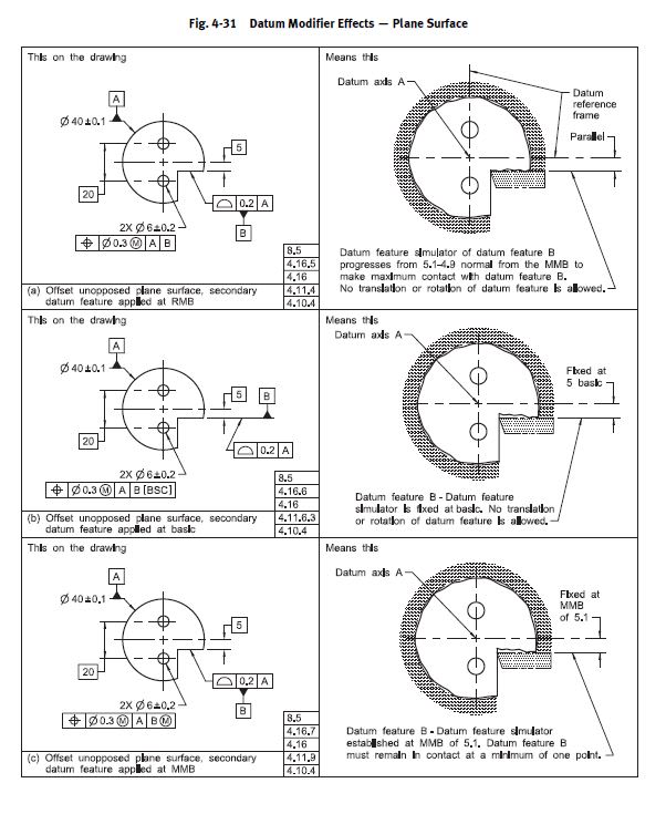
Considering fig. 4-31 that you posted above, illustrations (a) and (b), how would you describe the effect of the basic modifier on the tolerance zone of the 2 holes?
I am not sure how I would describe it myself, except that (b) is probably a more strict requirement. (a) allows some mobility of the B datum feature simulator, and indirectly also of the tolerance zones for the holes. Regardless in both (a) and (b) cases both location and orientation are fully controlled.

dtmbiz said:
The suggestion to use an offset modifier would be a misapplication for the datum features used in this thread. No offset datum feature is involved.

Given that there is a basic dimension between the A axis and B, what is your opinion on |A|B[BSC]|C|? Obviously, it would only be justified if it mimics the conditions of the functional assembly of the part.


chez311 said:
No - it only LOOKS like that because for a conical/tapered feature the effect of uniform offset and translation are the same

I would say that the axial translation causes the "normal offset" and not the other way around. If the relative movement of the true profile and the UAME simulator in your graphic is not axial and only looks that way, how would you show this concept if needed to demonstrate it using a physical "considered" external cone and another hollow conical "envelope" that is open at one end and closed by an apex at the other (made of transparent material for demonstration purposes)? Also, how would you display physically using those demonstration tools that there is no limit to the "normal offset/contraction" of the "envelope" cone towards the material of the considered cone (the "infinite contraction" that prevents a cone from being a FOS)?

 
Burunduk

In general I believe we are in agreement, havent had time to read your latest post in detail

Your OP turned into tangents with unrelated posts regarding the OP.

Considering tolerance zones are limited to the extent of the feature and the definitions below from previous posts shown below are not IAW (In Accordance With) the ASME Y14.5 2009 standard, from which those definitions and assertions have conclusions based on them, along with infinite expansion concept when were are discussing dimensioning of finite physical features; there is strong disagreement regarding the referenced standard and descriptions of geometric shapes and solids in contrast to below assertions. (New thread is warranted)(In a rush. apologies in advance, more later)

A cone doesn't have size?

A cone is more similar to a plane than a cylinder

A cone isn't a FOS because it doesn't have a UAME ?


chez311 said:
Quote (chez311)
A conical/tapered boundary expanded/contracted against (or uniformly offset toward) a conical/tapered feature unconstrained to any DRF will allow infinite expansion/contraction (uniform offset).


Quote (pylfrm, 8 Feb 19 01:54)
The "ability to escape" condition was my rough idea for how the concept of containment should be interpreted in this context, but let me back up a bit. The definitions provided by ASME Y14.5-2009 are not sufficiently robust to provide a definitive answer here. To arrive at a reasonable answer, we can attempt to patch up some of the gaps. To that end, consider the following replacement definitions:

Unrelated actual mating envelope: A theoretical envelope outside the material, uniformly offset from a feature's true profile as far as possible in the direction toward the material. The relationship between the true profile and the actual surface is otherwise unconstrained. If the material of the feature does not provide a limit to the offset, no unrelated actual mating envelope exists.

Feature of size: A feature with an unrelated actual mating envelope.

I think these definitions generally produce the same answers for cases that are clearly defined in the standard, and provide some additional clarity for cases that aren't. Thoughts?

Using these definitions, the conical feature (with or without the flat surface at the tip) is certainly not a feature of size. If you imagine the true profile starts out roughly aligned with the actual feature and an offset envelope progresses toward the material, it never reaches a point where it can't progress further. The feature just gets pushed away from the true profile.
 
dtmbiz,

Modifiers placed in conjunction with datum feature references ([BSC] or otherwise) only modify the behavior of datum feature simulators relative to each other. Tolerance zones are always held in basic relationship to the theoretical datums, and their behavior is dictated by the type of tolerance zone (ie: Orientation tolerance dictates orientation is held but not location, Position tolerance dictates both location and orientation are held). The referenced sections of the standard, with the exception of fig 4-31, have nothing to do with the [BSC] modifier specifically in conjunction with datum feature references.

Instead of expanding on this further, I'll just answer Burunduk's question to show how the [BSC] modifier works.

Considering fig. 4-31 that you posted above, illustrations (a) and (b), how would you describe the effect of the basic modifier on the tolerance zone of the 2 holes?
I am not sure how I would describe it myself, except that (b) is probably a more strict requirement. (a) allows some mobility of the B datum feature simulator, and indirectly also of the tolerance zones for the holes. Regardless in both (a) and (b) cases both location and orientation are fully controlled.

The bolded portion is correct, in both cases the requirement for basic location/orientation of the datum feature simulators is NOT overridden (as I said - can ONLY be done with customized DRF or datum translation). At first this may seem strange because in (a) B is allowed to progress and in (b) B is fixed. To understand this I think the 2018 version does a better job in defining this as when [BSC] is specified "the true geometric counterpart is defined by the basic dimensions of the true profile of the datum feature". In both (a) and (b) the true profile of the datum feature simulator (true geometric counterpart) is fixed in basic orientation and location, however in (a) the simulator is allowed to be uniformly offset normal to the true profile within its profile tolerance which is shown as progression from 5.1-4.9 . In (b) this uniform offset (progression) is not allowed and the simulator is defined by the true profile.

A cone doesn't have size?

A cone is more similar to a plane than a cylinder

A cone isn't a FOS because it doesn't have a UAME ?

No modified definition of Y14.5 is required to reach these conclusions.

A cone doesn't have size? A unique actual value for size per ASME Y14.5.1-1994 is not defined for conical features.

A cone is more similar to a plane than a cylinder. This comes from the geometry involved not any definition in the standard. A conical primary datum feature at RMB can be simulated by a fixed simulator, similar to a planar feature. Not so with a cylindrical feature (RMB requires an expanding simulator).

A cone isn't a FOS because it doesn't have a UAME ? If we are to consider the definitions for RFOS/IFOSa/IFOSb the only one where a conical feature with a conical boundary/envelope MIGHT fit would be IFOSb (RFOS requires a "cylindrical or spherical surface, a circular element, and a set of two opposed parallel elements or opposed parallel surfaces" and IFOSa requires an envelope which is a "sphere, cylinder, or pair of parallel planes"). That still leaves the requirement that the feature must be "contain or be contained by" this conical envelope, which I have shown multiple times is not the case. Therefore a conical feature with a conical envelope satisfies NONE of the available definitions, written exactly per the standard, for RFOS, IFOSa, or IFOSb - therefore it is NOT a FOS.
 
Status
Not open for further replies.

Part and Inventory Search

Sponsor