Continue to Site

Eng-Tips is the largest engineering community on the Internet

Intelligent Work Forums for Engineering Professionals

  • Congratulations cowski on being selected by the Eng-Tips community for having the most helpful posts in the forums last week. Way to Go!

Orientation of a center plane of a tapered feature 2

Status
Not open for further replies.

Burunduk

Mechanical
May 2, 2019
2,513
A designer applied perpendicularity feature control frame with the leader pointing to a centerline representing the center plane of an internal taper feature (a "pocket" with symmetrical non-parallel opposed surfaces). I don't consider this specification valid according to ASME Y14.5-2009 but I'm struggling to provide a good explanation of why perpendicularity shouldn't be used this way. The one use of perpendicularity I know when it is applied on a virtual, derived geometry (as opposed to an actual surface) is when a center plane/axis of a feature of size is controlled. It doesn't seem right in the context of a tapered feature, not associated with a size dimension - but I can't form a good argument why. A valid point is that a center plane can be derived from a tapered feature (for example, a datum plane derived from tapered datum feature), and I suppose that a way to evaluate the derived plane orientation relative to a DRF can be found. I need your help, please.
 
Replies continue below

Recommended for you

I would say that the bounding circles moving away or toward an apex can be relevant for a theoretical envelope, but this description is more detached from physical reality than the change in size of circular elements. Everything should be able to eventually be simulated physically, and physical devices don't work this way.

Aren't we are talking about two different ways of describing a single phenomenon, not two different for a device to work?


As usual, I have a hard time with this type of assertions. If a true profile of a cylindrical +/- toleranced feature is a cylinder of unspecified size, for sure the true profile can stay coincident with the cylindrical simulator during the entire process as well.

By "cylinder of unspecified diameter" I don't mean that you get to decide that it has some particular diameter.

A better way to describe this might be to say that the drawing's definition of the true profile is only partially complete. The drawing defines the true profile to be cylindrical by showing a cylinder in the views, but it does not complete the definition by specifying a basic diameter.

Maybe I still haven't succeeded in describing this well. Regardless, my point is that it doesn't make sense to say something is coincident with the true profile when the true profile is not fully defined.


Does it matter?

It does indeed matter that the datum feature simulator remains coincident with the true profile for the first type of behavior. The function of a datum feature reference is to provide some constraint of the relationship between the actual part and the theoretical geometry. For this to work there must be a defined relationship between the actual datum feature and the datum feature simulator, and there must be a defined relationship between the datum feature simulator and the theoretical geometry.


pylfrm
 
pylfrm said:
Aren't we are talking about two different ways of describing a single phenomenon, not two different for a device to work?

Yes we are. One of the descriptions conforms to the definition of the UAME in the standard ("similar perfect feature(s) counterpart expanded within an internal feature(s) or contracted about an external feature(s)"), the other doesn't. The one description that doesn't fit the UAME definition doesn't eliminate the one that does. It also happens that the one description that fits the definition is also more in line with how physical devices work (chucks, expanding mandrels...), so it allows more direct translation from theory to practice.

pylfrm said:
... my point is that it doesn't make sense to say something is coincident with the true profile when the true profile is not fully defined

Perhaps, but if the true profile is not fully defined (I would say completely undefined per the standard) for the cylindrical +/- case (probably the most common FOS application) maybe it is better to leave it off and just talk about contraction/expansion which can be generalized to all simulators of surfaces of revolution, and appears in the relevant definitions of concepts (UAME, datum feature RMB) in the standard?

pylfrm said:
It does indeed matter that the datum feature simulator remains coincident with the true profile for the first type of behavior. The function of a datum feature reference is to provide some constraint of the relationship between the actual part and the theoretical geometry. For this to work there must be a defined relationship between the actual datum feature and the datum feature simulator, and there must be a defined relationship between the datum feature simulator and the theoretical geometry.

I mostly agree with the above, but I think that tapered features are the special case where both the "first type" and "second type" of behavior are feasible, for each given feature.
 
Continuing with this reasoning and considering the specific example of an external cylindrical feature, "envelope with a uniform offset from the true profile" describes an infinite family of cylindrical envelopes. The only purpose of the true profile here is to fully define this family, and that can be achieved without the true profile itself being fully defined. In this case, "cylinder of unspecified diameter" is sufficient. One particular member of this family is the unrelated actual mating envelope, and that is the smallest one that can contain the feature while remaining outside its material.

Thank you, I think this is an excellent line of reasoning and I think it fits well. Not that I had an issue with the concept prior, however the "family" analogy is a good way of thinking of it.

In physical reality a simulator that behaves this way - essentially expands/contracts as specified by the UAME definition, is sometimes the only practical solution; imagine a conical feature connecting to a flat shoulder of a larger cylinder at its smaller end. Since there is no way to mate a conical simulator axially to this feature, A physical primary datum feature simulator must be a chuck-like device that will contract around the feature, obviously also representing the UAME. Isn't it "the second type of behavior"?

The physical limitations of simulation do not change the geometric realities discussed prior. Adjustment of this chuck-like device would be equivalent to axial adjustment/mating of a fixed simulator if material were not in the way. In this case you would be using a contracting simulator to approximate a fixed one due to physical limitations - the actual amount of contraction/offset is not important to the simulation so long as it is contracted to where the simulator extends over the entire length of the datum feature. No more would a series of fixed pins fit sequentially into a cylindrical hole be an example of the first type of behavior.

Since we are talking about theoretical geometry, a 180 degrees cone is perfectly flat, and all line elements on it are parallel and coplanar. Parallel line elements do not intersect, therefore there is no intersection point/vertex.

I'm not sure how you imagine a cone of any angle having line elements which are parallel but non-intersecting. Consider a cross section of a 179 degree cone containing its axis - you have two line segments with 179 degrees included angle. If this angle is changed to 180 degrees you now have two colinear lines (and yes by definition would also be parallel and coplanar as well) which could even be said to intersect at an infinite number of points all along their length.
 
chez311 said:
The physical limitations of simulation do not change the geometric realities discussed prior. Adjustment of this chuck-like device would be equivalent to axial adjustment/mating of a fixed simulator if material were not in the way. In this case you would be using a contracting simulator to approximate a fixed one due to physical limitations - the actual amount of contraction/offset is not important to the simulation so long as it is contracted to where the simulator extends over the entire length of the datum feature. No more would a series of fixed pins fit sequentially into a cylindrical hole be an example of the first type of behavior.

All this doesn't change the fact that a conical feature can be contained by an envelope/simulator that was contracted/expanded to contain it. This is all that's needed for cones to be inside the realm of UAMEs and FOS. It doesn't really matter if the simulation process is similar, equivalent to or different from other "types of behavior" in some aspect.

chez311 said:
Consider a cross section of a 179 degree cone containing its axis - you have two line segments with 179 degrees included angle. If this angle is changed to 180 degrees you now have two colinear lines (and yes by definition would also be parallel and coplanar as well) which could even be said to intersect at an infinite number of points all along their length.

I'd say that the two "colinear lines" in essence are equivalent to one single line along a flat plane. There are no intersections there. To have an intersection point between two lines you need lines at two different directions. No matter how you slice it, a 180° "cone" is not a cone and has no similarity to a cone. Just like if you enlarge a corner from say, two planes at 120° to each other to 180° you no longer have a corner, the "two" planes are coincident and actually it is one single plane. Saying that one plane is really two different features (or a flat taper) at a corner angle of 180° is just plain wrong.
 
All this doesn't change the fact that a conical feature can be contained by an envelope/simulator that was contracted/expanded to contain it. This is all that's needed for cones to be inside the realm of UAMEs and FOS. It doesn't really matter if the simulation process is similar, equivalent to or different from other "types of behavior" in some aspect.

It is equivalent in all aspects, save for perhaps likely some reduction in precision over whats much more easily achievable with a fixed simulator.

A single planar primary datum feature can be simulated by a movable simulator as well, it doesn't mean that movement or offset is in any way relevant to the simulation process.

I'd say that the two "colinear lines" in essence are equivalent to one single line along a flat plane. There are no intersections there.

I think we've overshot the point somewhere along the line.

Lets take a more simplified restatement of my previous example. Imagine a conical feature of adjustable angle (or maybe for a more simplistic but realistic, physical example - two linear rods attached with a joint) - if this is flattened to 180 degrees it will become equivalent to a planar feature (or a single linear one in the physical example). Whether you want to no longer call this a cone it matters not, the point is that geometrically there is no reason such a feature of 180 degrees included angle is not possible, and this feature would be exactly equivalent (not similar, but equivalent) to a planar one. Now reduce this angle towards 0 degrees - it will NEVER become equivalent to a cylindrical feature even as it infinitesimally approaches zero as long as it has this vertex and some included angle. In order to make a conical surface equivalent to a cylindrical one we would have to literally "break" the surface apart and remove this vertex/intersection (taking the simple physical example - remove the joint attaching the two linear rods).
 
chez311 said:
It is equivalent in all aspects, save for perhaps likely some reduction in precision over whats much more easily achievable with a fixed simulator.

Even if it is equivalent in all aspects, it doesn't take away from conformance to the Y14.5-2009 standard, FOS related concepts:

Was an adjustable simulator used according to para. 4.5.2 (f)? Check.

Was the feature contained by a simulator of "perfect" form and inverse shape of the specified geometry per the irregular FOS definition? Check.

chez311 said:
A single planar primary datum feature can be simulated by a movable simulator as well, it doesn't mean that movement or offset is in any way relevant to the simulation process.

I fully agree. That is also why I am against the "unlimited offset" argument.

As for the adjustable angle mechanism example of two rods connected by a joint, I realize it is intended as a 2D simplification of a cone, but can you simulate a truncated cone with it? No. Because it doesn't work without the physical joint representing the apex. Can a truncated cone exist? Yes. With this specific physical mechanism example, you portray the apex point as a crucial feature that it really isn't. The apex point is defined by and dependent on the characteristics of a given conical surface (base size and included angle), but not vice versa - i.e, the conical surface doesn't depend on the existence of an apex. The only mandatory theoretical geometry outside of the surface outline needed to fully define a cone is the axis. Without the axis, there can be no surface of revolution such as a cone or a cylinder. The axis of a theoretically perfect surface of revolution crosses the centers of all the circular elements that the surface is composed of. In that sense, a cylinder can be viewed as a special case of a cone with 0° slope (I'm aware that this is not entirely "by the book"). If the slope angle is changed to 90° (180° included angle) then the axis becomes of zero length; the only meaningful length of any axis of a theoretically perfect feature is the portion at which it connects center points of cross-sections of the theoretical surface which it is related to. This effectively eliminates the existence of a surface of revolution - there is nothing to revolve around, therefore the resulting geometry is undefined as a surface of revolution. If it is no longer a surface of revolution then there is certainly no equivalence with a cone.
 
Was an adjustable simulator used according to para. 4.5.2 (f)? Check.

Was the feature contained by a simulator of "perfect" form and inverse shape of the specified geometry per the irregular FOS definition? Check.

If you're asserting that this is a valid example of a UAME for an IFOSb then you've left out the fact that such an envelope must be of largest (internal feature) or smallest (external feature) size. Regardless of whether size is defined for a conical feature, largest/smallest requires at the very least a maximum/minimum limit - where is this maximum/minimum limit for a conical primary datum feature simulator which results in identical simulation now matter how much adjustment is made to the "size" ?

A single planar primary datum feature can be simulated by a movable simulator as well, it doesn't mean that movement or offset is in any way relevant to the simulation process.
I fully agree. That is also why I am against the "unlimited offset" argument.

You're going to have to explain to me how these two statements jive. You agree that offset (and I hope from our conversation thus far you realize by offset I meant all analogous behavior for a conical simulator ie: axial movement and contraction/expansion) is not necessarily relevant to the simulation process for a conical feature but still say that an offsetting simulator for a conical feature is an example of valid "second type of behavior" ?

but can you simulate a truncated cone with it? No. Because it doesn't work without the physical joint representing the apex.

A simulator for a truncated cone does not have to be a truncated cone. A fully formed cone as well as a truncated cone would result in equivalent simulation of a conical primary datum feature, I'm not clear on why you believe otherwise.

If you're saying that a fully formed cone doesn't mimic the behavior of a truncated cone, it doesn't matter if this apex is physical or theoretical - such an intersection can be derived and the behavior is the same.

With this specific physical mechanism example, you portray the apex point as a crucial feature that it really isn't. The apex point is defined by and dependent on the characteristics of a given conical surface (base size and included angle), but not vice versa - i.e, the conical surface doesn't depend on the existence of an apex. The only mandatory theoretical geometry outside of the surface outline needed to fully define a cone is the axis.[

It certainly does. A truncated cone has no physical axis or vertex - these are both theoretical geometry existing within or without the material, the fact that you can't see or touch them does not matter. I only utilized a physical example of a joint to provide something physical to better imagine my point. In a truncated cone this vertex is theoretical but an intersection still exists. In both cases the axis is fully theoretical but you clearly have no trouble acknowledging such an axis exists, why you can't apply the same logic to the apex is mystifying.

In that sense, a cylinder can be viewed as a special case of a cone with 0° slope (I'm aware that this is not entirely "by the book")

I'm sorry, I'm going to have to strongly disagree with this - even though as you can tell I'm a supporter of creative interpretations. Switching the convention** to slope of the line segments (half the included angle) does not change the requirement that the shape must have a vertex/intersection point which at which the line segments meet to create the included angle. Two parallel, non-intersecting line segments such as would be found on a cylindrical feature do not have an vertex/intersection point by any definition and therefore no included angle which is the basic requirement for a cone no matter how far I might stretch the definition.

Below is a simplistic version of what I mean. A through D have included angles and intersection points - A being 180 degrees, D being 0 degrees, and C/D being somewhere in between. E has no intersection and does not have an included angle. While not something I have an issue with personally, I understand the difficulty in discussing cones or intersection points with 0 or 180 degree included angles - but to suddenly make the leap to a cylinder (E) where there is not even the possibility of an intersection point to me follows neither logically nor geometrically.

vertices_z0klaj.jpg


A cylinder of any nonzero diameter is not a cone in any sense or "special case". The only thing I will concede is that a cone of 0 degree included angle is a line which MAYBE one could say is a cylinder with a diameter of zero, but I don't see much use in discussing cylinders having no diameter especially as this logic does not apply to any other cylinder for as soon it has any nonzero diameter it is absolutely not a cone (no intersection/included angle). Though if I'm to go by your previous statements if you do have issues equating a 180 degree included angle cone with a plane I would think you have the same issues equating a 0 degree included angle cone with a line - the fact that you would make the leap from a 0 degree cone to a cylinder of any diameter seems incongruent (though as I said equating it to anything other than a cylinder of zero diameter is not supported by the geometry involved).

If the slope angle is changed to 90° (180° included angle) then the axis becomes of zero length; the only meaningful length of any axis of a theoretically perfect feature is the portion at which it connects center points of cross-sections of the theoretical surface which it is related to. This effectively eliminates the existence of a surface of revolution - there is nothing to revolve around, therefore the resulting geometry is undefined as a surface of revolution. If it is no longer a surface of revolution then there is certainly no equivalence with a cone.

What I personally believe is that the axis is really of infinite length - as long as it bisects the angle theres no reason to limit it to the length of the feature. So a planar feature could have an axis consisting of any line normal to the surface. But perhaps thats a bit of a stretch for most people. Your statement that there is "nothing to revolve around" could be countered with the existence of such an infinite axis, or even without it I see no reason that anything existing in the same plane could be revolved around a single point instead of an axis. Do you not agree that a point could be revolved around another point to create a circle? Same concept.

Setting all that aside for the moment, can we agree that geometrically there exist features of 0 degrees included angle, 180 degrees included angle, and everything in-between? Going by stricter definitions a cone is the set of possible features having an included angle between 0 and 180 degrees, bounded on one end by a shape having included 0 degree angle which is a line (or a cylinder with a diameter of zero) and on the other end by a shape having included 180 degree angle which is a plane.

Nowhere within that set (between 0-180 degrees) or the bounds (0 and 180 degrees exactly) exists a cylinder of any NONzero diameter which is why I disagree with geometrically equating a cone and cylinder of nonzero diameter. Conversely, one of those bounds (180 degrees) is a plane which is why I have asserted the similarities between a cone and plane.


**Edit - I see you may be referring to the calculation for (D-d)/L you mentioned in the other thread. First, you added "degrees" to the slope which is not correct. It is degrees or non-dimensional slope, not "0 degree slope". Second that calculation is the amount of "taper" which must be halved to get the actual slope of the line segments. This tells us nothing we dont already know - that a cylinder (D-d)/L would be zero which means it has zero taper and the line segments which it consists of have zero slope. For a cylinder of non-zero diameter these line segments are still parallel and non-intersecting and the resulting shape has no intersection point/vertex which is required for a cone. The entirety of my response stands as stated with no modifications needed.
 
Perhaps, but if the true profile is not fully defined (I would say completely undefined per the standard) for the cylindrical +/- case (probably the most common FOS application) maybe it is better to leave it off and just talk about contraction/expansion which can be generalized to all simulators of surfaces of revolution, and appears in the relevant definitions of concepts (UAME, datum feature RMB) in the standard?

I would agree that it may be better to avoid involving "true profile" and "uniform normal offset" if we were only discussing cylinders, spheres, and widths between parallel planes. I'm generally content to talk about contraction/expansion of such envelopes, although I usually prefer "smallest circumscribed" / "largest inscribed" or similar terminology because it describes the answer instead of a process which is not actually relevant.

The generalization of contraction/expansion to a cone is equivalent to axial translation of the surface, possibly combined with some alteration of the boundaries of the surface if they exist. In this case I think the boundaries of the surface might reasonably be said to contract or expand, but the surface itself cannot.

If a bounded envelope is considered, the boundaries must be beyond the actual feature. This means the envelope surface is the only thing that interacts with the actual part surface, and the boundaries are irrelevant. I don't think it makes much sense to use terminology that only applies to an irrelevant or nonexistent portion of what you're discussing.


All this doesn't change the fact that a conical feature can be contained by an envelope/simulator that was contracted/expanded to contain it. This is all that's needed for cones to be inside the realm of UAMEs and FOS. It doesn't really matter if the simulation process is similar, equivalent to or different from other "types of behavior" in some aspect.

Actual physical chuck jaws can certainly be described as contracting or expanding with respect to each other, but the theoretical conical datum feature simulator surface that they are approximating does not change. The only change is that they approximate a different portion of that surface.


Could you provide some examples of surfaces (or sets of surfaces) that you would say do not have UAMEs?


pylfrm
 
chez311 said:
If you're asserting that this is a valid example of a UAME for an IFOSb then you've left out the fact that such an envelope must be of largest (internal feature) or smallest (external feature) size. Regardless of whether size is defined for a conical feature, largest/smallest requires at the very least a maximum/minimum limit - where is this maximum/minimum limit for a conical primary datum feature simulator which results in identical simulation now matter how much adjustment is made to the "size" ?

If a conical adjustable device such as this expanding/contracting collet is used as a simulator, largest/smallest is determinable. In this case, the theoretic "smallest contracted" is actually at the physical "largest expanded" state of the "envelope", because as the external cone is engaged the collet expands until it fully contains it. The external cylindrical diameter of the collet can be measured as a gage-related indication for feature size. Measured value is unimportant but maximum/minimum can be detected. The conical feature itself doesn't have one specific size but it consists of circular elements which are all regular features of size. If it is necessary to provide a single calculable value for the size of the entire cone in a repeatable manner (per produced feature) I am sure creative methods to establish such value can be thought-out.


chez311 said:
You're going to have to explain to me how these two statements jive. You agree that offset (and I hope from our conversation thus far you realize by offset I meant all analogous behavior for a conical simulator ie: axial movement and contraction/expansion) is not necessarily relevant to the simulation process for a conical feature but still say that an offsetting simulator for a conical feature is an example of valid "second type of behavior" ?

I see those things differently - contraction/expansion is not the same thing as "offset", they are not equivalent or interchangeable and do not belong in the same "pile". "Offset" implies some fixed, location-defined reference from which it is being measured. This reference has been referred to as true profile - a concept undefined for all regular features of size. For me the behavior required for a primary datum feature of size simulator and for a UAME is simply "contraction/expansion", like in the example in the above link. A plane simulator that translates relative to some reference is not of the same "type of behavior" as an expanding/contracting simulator.

You disagree that a cylinder can be considered a 0° taper. I disagree as much that a 180° "cone" is a cone. A cylinder lacks an apex and a plane (180° "cone") lacks an axis. If the axis can be anywhere on the plane it is not an axis, just a normal. An axis is a straight line that should cross the related theoretical feature at its center and provide a direction for the extrusion of its surface. Such center and direction do not exist for a plane.

Let us not forget that all Y14.5 concepts should eventually be applied to physical parts. Cylinders are often produced slightly conical and yet an axis can still be determined, and that is the main purpose of the UAME. It is true that for a nominally cylindrical feature the simulator is cylindrical, but if a slight taper is specified for the considered feature the simulator can be adjusted to accommodate it and function the same way. Plane surfaces are sometimes produced slightly conical too, such as in the case of an end face of a shaft produced by face turning on a lathe. I doubt anyone ever thought of even trying to determine an axis (apply UAME) for one of those.

pylfrm said:
In this case I think the boundaries of the surface might reasonably be said to contract or expand, but the surface itself cannot.

...
I don't think it makes much sense to use terminology that only applies to an irrelevant or nonexistent portion of what you're discussing.

If I understand correctly the terminology applied to nonexistent portion of what we are discussing is expansion/contraction of a conical surface.
The expansion of the surface of a truncated cone is the increase/reduction of the sizes of all the circular elements of the surface proportionally (maintaining a constant included angle). Was I using irrelevant terminology now? The same concept may be "equivalent" geometrically to considering different segments of an infinite cone - wherever you slice it you get different sizes. But, parts and features are finite.

 
If a conical adjustable device such as this expanding/contracting collet is used as a simulator, largest/smallest is determinable.

This product is intended to grip an internal cylindrical surface of the workpiece. Which of its surfaces are you talking about using as a simulator, and what would it be simulating?


For me the behavior required for a primary datum feature of size simulator and for a UAME is simply "contraction/expansion"

In ASME Y14.5-2009 Fig. 8-20, would you say the feature with the profile tolerance would have a UAME? If so, what would the UAME geometry be if the 40, 55, and 4X R5 dimensions were actually produced as 40.9, 56.1, and 4X R3 respectively?


If I understand correctly the terminology applied to nonexistent portion of what we are discussing is expansion/contraction of a conical surface.

The terminology: contraction/expansion.
What we're discussing: an envelope proposed to be a UAME.
The irrelevant or nonexistent portion: boundaries of that envelope.


The expansion of the surface of a truncated cone is the increase/reduction of the sizes of all the circular elements of the surface proportionally (maintaining a constant included angle). Was I using irrelevant terminology now?

I assume you mean comparing the sizes of circular elements which are equal axial distances from the truncation of their respective cones.

I wouldn't (and didn't) say you were "using irrelevant terminology". I would say you're involving irrelevant things in the discussion.


pylfrm
 
pylfrm said:
This product is intended to grip an internal cylindrical surface of the workpiece. Which of its surfaces are you talking about using as a simulator, and what would it be simulating?

Sorry for not clarifying: I didn't mean using the exact same product "as is" but a device that works by the same principle as the expanding collet to which the conical feature in that product is mated. You have surely noticed the conical feature in that mechanism. It can be engaged manually into a device that works like the expanding part. It would be important to make sure the entire conical feature is covered by the simulator. For that purpose, the simulator should be longer than the conical feature and some kind of stoppers could be adjusted to the expanding components at the side of the small end to prevent the considered feature from overhanging outside the simulator. The feature should be engaged very lightly against those stoppers to prevent the stoppers from acting as an orientation constraint. Once the cone is fully engaged until minimum contact is made with the stoppers the simulation is finished. Replace a given considered cone with a larger cone of same length and the device will expand to a larger external diameter (the one intended to grip a workpiece ID in the example product) at full engagement. I hope this clarifies what I failed to communicate in the previous post.

Good point regarding fig. 8-20 I will have to give it some thought before answering. This is exactly why I find the discussions here broadening.
 
The external cylindrical diameter of the collet can be measured as a gage-related indication for feature size. Measured value is unimportant but maximum/minimum can be detected. The conical feature itself doesn't have one specific size but it consists of circular elements which are all regular features of size.

Minimum/maximum must be of the geometry in question not of some other feature on the simulator not directly implied by the feature geometry unless accompanied by a note specifically stating as much. Regardless measurement of some other non-conical feature on the simulator or use of circular elements does not provide a different answer to my question "where is this maximum/minimum limit for a conical primary datum feature simulator which results in identical simulation now matter how much adjustment is made to the "size" ?". There is no minimum/maximum limit for a conical primary datum feature simulated by a movable simulator and therefore would be no minimum/maximum limit for any circular element (or any other element) of said simulator.

You describe a simulator in your post on (18 Dec 19 08:31). Again, as with any example of an adjustable conical simulator, if the simulator has sufficient height/truncation past the feature(s) which it simulates then no "expansion/contraction" is necessary. Possible, yes - but not necessary.

A plane simulator that translates relative to some reference is not of the same "type of behavior" as an expanding/contracting simulator.

I see no reason it couldn't be. The fact that equivalent behavior is observed when a fixed conical simulator translates axially as well as when an adjustable conical simulator is "expanded" should tell you as much. Additionally if you consider a width-shaped simulator which expands, is not each side considered separately translating relative to some reference? The divisions between these behaviors are not as simple as one might expect. Thats not to say that for a primary datum feature this would be a VALID example of such behavior, as it would have no limit, but the behavior is possible nonetheless.

You disagree that a cylinder can be considered a 0° taper. I disagree as much that a 180° "cone" is a cone. A cylinder lacks an apex and a plane (180° "cone") lacks an axis. If the axis can be anywhere on the plane it is not an axis, just a normal.

An axis would bisect the included angle. In the case of a 180 degree angle that bisected angle results in a line at a 90 degree angle to the surface, which is also by definition normal to the surface. They could be one and the same. The fact that there is an infinite number of such lines makes it difficult to comprehend but not geometrically impossible - it simply results in an infinite number of solutions instead of one.

Again, I've already conceded that my interpretation may challenge the generally accepted notion of what a cone is and may be hard to swallow. I don't really expect you to agree with me on this point. You've skipped over the more relevant portion of my response.

The main thrust of my statement was that the set of conical features having included angle between 0 and 180 degrees is bounded on either end by shapes having 0 and 180 degrees exactly. Even if you don't call either of these bounds cones of any type, my point was to show that a plane is represented by one of these bounds (180 degrees). Not similar to or approximately, but exactly. This bound is achieved by simply changing the included angle from 179 to 180 degrees and the existence of the vertex can be maintained - the fact that said vertex can be any point on the resulting plane doesn't matter. There is nothing preventing the transition of a shape with a vertex to make this transition from 179 to 180 degrees - neither theoretically nor physically as I showed. Neither of these bounds is a cylinder of nonzero diameter and it is impossible to create a cylinder of nonzero diameter from a shape having an included angle and vertex - this is true both theoretically and physically.

Let us not forget that all Y14.5 concepts should eventually be applied to physical parts. Cylinders are often produced slightly conical and yet an axis can still be determined, and that is the main purpose of the UAME. It is true that for a nominally cylindrical feature the simulator is cylindrical, but if a slight taper is specified for the considered feature the simulator can be adjusted to accommodate it and function the same way.

I never said an axis cannot be derived from a conical shape. Derivation of an axis is not necessarily the main "job" of a UAME. Not all UAME even have a single definitive axis for example Y14.5-2009 fig 8-24.

Its tough to tell exactly what you mean by that last sentence.

If we assume by "specified" you mean that a nominally cylindrical feature has variation which results in conicity and by "adjusted" you mean expansion/contraction of this nominally cylindrical simulator, your comparison does not support your point. Even when we consider the theoretical geometry, a cylindrical envelope will find a minimum/maximum on a conical feature.

If we assume by "specified" you mean specified on the drawing as a slight taper, and a matching tapered datum feature simulator would be used for simulation and are implying that they would function the same as a perfectly cylindrical simulator in the real world - this does not make for a rigorous definition. The mathematical and geometric concepts contained in Y14.5 must be rigorous and apply both for the theoretical and physical. The fact that due to friction effects small amounts of taper behave in the same way in the real world (1) falls apart when the theoretical geometry is considered (see below on what the standard says about theoretical datum feature simulators) and (2) falls apart in the physical world when non-trivial amounts of taper are considered.

Alternately, if you mean to imply that a nominally cylindrical physical datum feature simulator produced with some slight taper error will function similarly to one produced with no taper in the physical world, then this is not the purview of Y14.5 - this is explicitly stated several times in the standard that the concepts in Y14.5 only apply to theoretical datum feature simulators and does not take into account such error.

Y14.5-2009 section 4.6 said:
The principles in this Standard are based on theoretical datum feature simulators and do not take into account any tolerances or error in the physical datum feature simulators. See ASME Y14.43.
 
chez311 said:
Regardless measurement of some other non-conical feature on the simulator or use of circular elements does not provide a different answer to my question "where is this maximum/minimum limit for a conical primary datum feature simulator which results in identical simulation now matter how much adjustment is made to the "size"?

Finding a specific value for maximum/minimum for the expansion/contraction is a process related task and it is not required by Y14.5. The simulation can take place per my example with the expanding collet. Once the cone is fully contained you get the "minimum contracted" envelope. As I already said you know that it's the "minimum contracted" because for a larger cone (of same length) you will get a larger envelope: the simulator will end up with larger diameters all along the conical internal surface(s) (consider those if you refuse to use the external cylindrical surface of the gage as an indicator). The expanding mechanism is actually required by Y14.5 once we want to treat the cone as a feature of size, per para. 4.5.2 (f). If we attempt to treat it as FOS and succeed at it - it is FOS.

Also, you cannot separate the circular elements from the conical surface because the conical surface IS all those circular elements, and all those elements have size, regardless of their locations. Imagine a part with just 3 features: a conical surface and two flat parallel surfaces where the base and the small end are. For full dimensioning, you could have the included angle, the length between the two flat ends, and the diameter on either the small or large end. The diameter would belong to the conical surface because flat surfaces can't have diameters defined for them. The assertion that "a cone is defined by the included angle alone" is not true because for the above-mentioned cone there would be a missing dimension without the size dimension. "Size" - that's how such dimensions/related tolerances are referred to by the standard - 8.4.2 Conicity: " A profile tolerance may be specified to control the conicity of a surface in two ways: as an independent control of form as in Fig. 8-17 (Means this mentioning "limits of size"), or as combinations of size, form, orientation, and location, as in Fig. 8-18. "

Continuing on your point about transition from 179° to 180° - arguably we could have a truncated cone with an adjustable included angle and a constant small end diameter as the theoretical geometry. You could have smooth transition from say 30° included angle, gradually decreasing until 0° (cylinder). The apex will disappear but nevertheless, such a transition is possible. When you change the included angle to 180° both the apex and axis disappear. If you have an infinite number of possibilities to derive some geometry that geometry is called "ambiguous".

Edit: As for the slightly tapered feature - I did mean "specified" as in drawing specification and the "simulator adjusted" having the included angle defined in the drawing. I disagree that this is not rigorous because it can work for any included angle and the simulation is not friction dependent. The taper being "slight" is just to emphasize the difference from a cylinder not being that great. One point that you brought up on this matter is particularly interesting: you say that a conical feature can always successfully limit a cylindrical simulator:

" Even when we consider the theoretical geometry, a cylindrical envelope will find a minimum/maximum on a conical feature. "

Then perhaps it is IFOS type (a)?

I still owe pylfrm an answer about fig. 8-20.
 
Finding a specific value for maximum/minimum for the expansion/contraction is a process related task and it is not required by Y14.5

ASME Y14.5-2009 said:
1.3.25 Envelope, Actual Mating
envelope, actual mating: this envelope is outside the material. A similar perfect feature(s) counterpart of smallest size that can be contracted about an external feature(s) or largest size that can be expanded within an internal feature(s) so that it coincides with the surface(s) at the highest points. Two types of actual mating envelopes — unrelated and related — are described in paras. 1.3.25.1 and 1.3.25.2.

Its right there in the definition. The process to find it is outside Y14.5 but such a maximum/minimum must exist.

Once the cone is fully contained you get the "minimum contracted" envelope. As I already said you know that it's the "minimum contracted" because for a larger cone (of same length) you will get a larger envelope: the simulator will end up with larger diameters all along the conical internal surface(s)

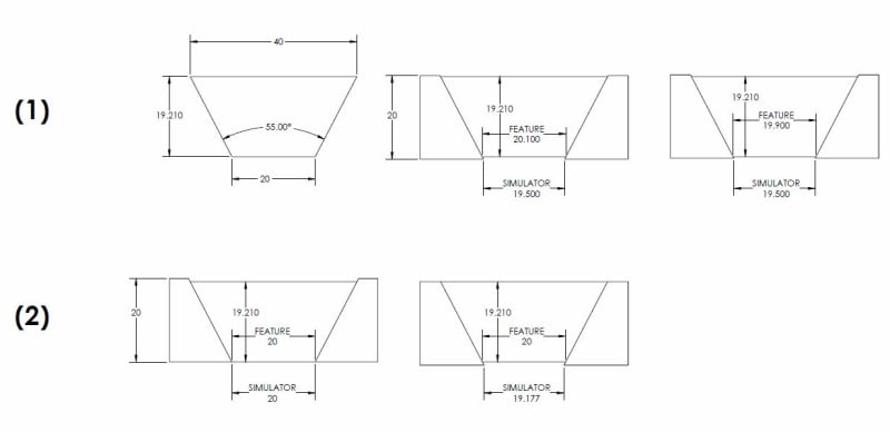
See below. (1) shows that an adjustable simulator could handle different truncations of the conical feature of interest with no need to "contract" it. For (2) which one is the minimum point of "contraction" when both provide equivalent simulation? Both are "contained" per your definition.

FIXED_VS_ADJUSTABLE_SIMULATOR_t0butp.jpg


Continuing on your point about transition from 179° to 180° - arguably we could have a truncated cone with an adjustable included angle as the theoretical geometry. You could have smooth transition from say 30° included angle, gradually decreasing until 0° (cylinder). The apex will disappear but nevertheless, such a transition is possible. When you change the included angle to 180° both the apex and axis disappear. If you have an infinite number of possibilities to derive some geometry that geometry is called "ambiguous".

If by "disappear" you mean indistinguishable but still exists, then we agree.

If by "disappear" you mean it vanishes or somehow ceases to exist, then I do not agree. The below assumes the latter.

The apex is a point. A point has no size. A line consists of an infinite number of points. A plane also consists of an infinite number of points. A line and plane also have no size. The apex does not disappear, in both the 0 and 180 degree cases it just becomes indistinguishable from any other point along a line (in the 0 degreee case) or on a plane (180 degree case). If you have a black surface and you make a mark on it with black ink, does that mean the mark does not exist or has "disappeared" ? No, its just indistinguishable from any other part of the black surface. As with the physical case with two rods connected by a joint - if positioned at 180 degrees the joint may not be distinguishable from any other part of the two rods but it certainly exists. The implication that it "disappears" or ceases to exist is just not logical.

This ambiguity would only come into play if you attempted to define a single axis/vertex for such a feature. I was just asserting the geometric similarities.

I disagree that this is not rigorous because it can work for any included angle and the simulation is not friction dependent.

You said it will "function in the same way" as a cylindrical simulator. It will not for any included angle in the theoretical world. It will also not in the physical world for anything more than a few degrees of taper. A cylindrical simulator is expanded/contracted until it cannot be expanded further. Try the same with a cone - all you will succeed in doing is pushing the part out of the simulator. The behavior is similar to expansion/contraction but the function is NOT the same as it will never achieve a point at which no further expansion/contraction is possible.

This lies at the heart of my issue with any argument saying that a cone/taper is a FOS. With a cylindrical feature one can expand/contract a simulator until the feature itself stops the expansion/contraction. Put a round part in a lathe chuck jaw. Once the jaws clamp around the part, I don't care how hard you tighten it, you will not succeed in further contraction. Same with a square part in a vice. This behavior cannot be replicated with a conical feature and conical simulator.

you say that a conical feature can always successfully limit a cylindrical simulator [...] Then perhaps it is IFOS type (a)?

A conical feature has by default a conical boundary, I do not waiver from my assertion this is not a FOS of any type. A conical feature with a SPECIFIED (ie: by a note or such) cylindrical boundary could be considered a IFOSa, I already said as much very early in this discussion.
 
The adjustable conical simulator will have to contract as much as it takes to make full contact around the conical part. Once it does, further contraction is not necessary. Rejecting a UAME based on the possibility of the simulator to contract further after completing the process is rejecting it based on some mechanical behavior related to the process of the simulation, not to the theory of dimensioning and tolerancing.

Figure (1) in your sketch shows that if the simulator's small end is larger than 20.1 (middle image) or 19.9 (right side image) it will have to contract to fully contain the feature.

Figure (2) shows 2 different fully acceptable simulation results, identical ones. No need to choose among them: assuming no form error (for simplification) in both cases dia. 20 of the feature is precisely simulated by did. 20 of the simulator, and similarly each and every local diameter on the feature is simulated by an equal diameter on the simulator.

If you prefer to call the apex and axis of a 180° "cone" indistinguishable rather than ambiguous then so be it. I'd rather call it imaginary (made up). If you look at a black surface you can imagine that there is a black ink mark on it, which may be there and may not. If you make a truncated cone into a nonzero size cylinder by folding the included angle about a fixed size truncation at least the axis doesn't disappear. You may disagree but I find the apex less important. When you construct a conical feature on a CAD program by creating a "revolute" you need to define the feature outline and an axis of revolution. The apex simply results from the geometry you create. I find more similarity between a cone and a feature with a distinguishable axis than with a flat plane with an infinite number of made-up axes and apexes. Also, both cylinders and cones are dimensioned with diameters.

"A conical feature has by default a conical boundary." this is what I tend to think too, but what is the shape of the boundary of a hex screw head?
 
Imagine a part with just 3 features: a conical surface and two flat parallel surfaces where the base and the small end are. For full dimensioning, you could have the included angle, the length between the two flat ends, and the diameter on either the small or large end. The diameter would belong to the conical surface because flat surfaces can't have diameters defined for them.

The diameter dimension does not belong to one surface or the other. It applies to the intersection of the two surfaces, and it defines the relationship between them. That relationship could be equivalently defined by a dimension from the apex of the cone to the flat surface.


The assertion that "a cone is defined by the included angle alone" is not true because for the above-mentioned cone there would be a missing dimension without the size dimension.

In this assertion, "a cone" refers to an unbounded surface. Hopefully the following is enough to convince you that it's true:

The following equation defines a conical surface in a Cartesian coordinate system:

z = sqrt(x^2 + y^2) / 0.15​

Note that the constant 0.15 is a pure number, not a length, and that it is the only constant involved.

If you interpret "a cone" as referring to a surface and boundaries of that surface, then of course the assertion would be false. The reasonable conclusion is that you shouldn't interpret it that way.

Would you say that datum feature A in ASME Y14.5-2009 Fig. 4-4 is not fully defined because there is no dimension for the outside diameter of the flange? I certainly wouldn't. I'd say that it's fully defined (as planar) by the fact that the drawing shows it as such and doesn't specify otherwise. No dimensions are required.

What about datum feature A in ASME Y14.5-2009 Fig. 4-34? I'd say that it's fully defined (as cylindrical with a basic radius of 4) by the fact that the drawing shows a cylindrical form and provides the basic dimension for its size. The relationship between it and the 12 adjacent planar surfaces is not fully defined, but that's a separate concern.


"Size" - that's how such dimensions/related tolerances are referred to by the standard - 8.4.2 Conicity: " A profile tolerance may be specified to control the conicity of a surface in two ways: as an independent control of form as in Fig. 8-17 (Means this mentioning "limits of size"), or as combinations of size, form, orientation, and location, as in Fig. 8-18. "

The "limits of size" mentioned in those figures are only defined in relation to the planar surfaces, using a method similar to that shown in Fig. 2-21. I think it's reasonable enough to discuss the "size" of a conical surface in that context, but not of a conical surface considered in isolation.

Side note: Fig. 8-18 is somewhat strange because the reference to datum feature B could be eliminated without changing the meaning of the profile tolerance.


I still owe pylfrm an answer about fig. 8-20.

I hope you will also consider responding to the question at the end of my 17 Dec 19 03:44 post.


pylfrm
 
pylfrm said:
In ASME Y14.5-2009 Fig. 8-20, would you say the feature with the profile tolerance would have a UAME? If so, what would the UAME geometry be if the 40, 55, and 4X R5 dimensions were actually produced as 40.9, 56.1, and 4X R3 respectively?

The UAME geometry for the actually produced feature would be 40.8 X 56.1 with radii: 4X R5.1. This is what the final product of the UAME simulation should be. How does it get to these dimensions is not really relevant. It is an internal feature so it should expand. It can start expanding from a theoretical feature of any shape and initial dimensions that is within the empty space of the internal feature. There is no offset required and certainly not "uniform offset". The expanding envelope shouldn't have any relationship with the true profile before the simulation process is completed. Having a constant relationship with the true profile during simulation will mean that the "unrelated" AME is not really unrelated.

pylfrm said:
If you interpret "a cone" as referring to a surface and boundaries of that surface, then of course the assertion would be false. The reasonable conclusion is that you shouldn't interpret it that way.

I don't find any other way of interpretation useful in the realm of dimensioning and tolerancing. Have you ever dimensioned and defined tolerances on a drawing for an isolated and infinite conical feature?

pylfrm said:
Would you say that datum feature A in ASME Y14.5-2009 Fig. 4-4 is not fully defined because there is no dimension for the outside diameter of the flange? I certainly wouldn't. I'd say that it's fully defined (as planar) by the fact that the drawing shows it as such and doesn't specify otherwise. No dimensions are required.

What about datum feature A in ASME Y14.5-2009 Fig. 4-34? I'd say that it's fully defined (as cylindrical with a basic radius of 4) by the fact that the drawing shows a cylindrical form and provides the basic dimension for its size.

I suppose then that you would find the countersink in fig. 1-39 fully dimensioned if dia. 10 was not specified, right? The 90° included angle should be enough. Is this figure overdimensioned?


pylfrm said:
Burunduk said:
Imagine a part with just 3 features: a conical surface and two flat parallel surfaces where the base and the small end are. For full dimensioning, you could have the included angle, the length between the two flat ends, and the diameter on either the small or large end. The diameter would belong to the conical surface because flat surfaces can't have diameters defined for them.
The diameter dimension does not belong to one surface or the other. It applies to the intersection of the two surfaces, and it defines the relationship between them. That relationship could be equivalently defined by a dimension from the apex of the cone to the flat surface.

The diameter indeed applies to the intersection of two surfaces, but in conjunction with the included angle, it also defines the nominal size of every single local circular element along the surface.
The dimension from the apex to the flat surface would do the same thing, thus it is also a specification of the size of the feature. Another way to dimension that cone could be specifying a diameter at some place along the conical feature at a fixed distance from the apex, and 2 distances from that circular element, one to the base and the other to the truncation. Again the size of every circular element of the surface is defined, thus the size of the entire feature is defined, this time without involving diameters of intersections with other features.


pylfrm said:
In ASME Y14.5-2009 Fig. 8-20, would you say the feature with the profile tolerance would have a UAME? If so, what would the UAME geometry be if the 40, 55, and 4X R5 dimensions were actually produced as 40.9, 56.1, and 4X R3 respectively?

The UAME geometry for the actually produced feature would be 40.8 X 56.1 with radii: 4X R5.1.

Now imagine this feature is identified as datum feature D, and the current composite profile tolerance is replaced with [box]profile[/box][box]10[/box][box]D[/box]. You would say the datum feature simulator is the UAME that you just described, right?

What would be the spatial relationship between the UAME and the true profile that the tolerance is based on?

(Making the toleranced feature be the primary datum feature reference of its own tolerance is the simplest way I can think of to ask this question. Please forgive the strangeness of the scheme.)


I don't find any other way of interpretation useful in the realm of dimensioning and tolerancing. Have you ever dimensioned and defined tolerances on a drawing for an isolated and infinite conical feature?

I think that's how it usually works. Maybe I misunderstand your question though.

Consider ASME Y14.5-2009 Fig. 4-44 for example. As far as the profile tolerance is concerned, all that matters is that the basic included angle is defined. The boundaries of the surface (theoretical or actual) are irrelevant. The drawing shows the portion of the cone between roughly 25 mm and 50 mm from the apex, but the tolerance controls whatever portion actually exists. A part could be produced that actually has the portion between 10 mm and 20 mm from the apex, and it would meet the tolerance if it has the correct included angle.

Similarly, the boundaries of the surface are not relevant to its use as a datum feature reference. The extent of the datum feature simulator is sufficient to cover the entire actual feature, regardless of how that compares to the theoretical geometry.


I suppose then that you would find the countersink in fig. 1-39 fully dimensioned if dia. 10 was not specified, right? The 90° included angle should be enough. Is this figure overdimensioned?

Countersinks are mainly defined in relation to the adjacent surfaces, so no, it would not be fully dimensioned in that sense. The 90° included angle is enough to fully define the form of the conical surface itself though. If that dimension were basic, the true profile of the surface would be fully defined and a profile tolerance could be applied.

No, the unmodified figure is not over-dimensioned.


pylfrm
 

pylfrm said:
Now imagine this feature is identified as datum feature D, and the current composite profile tolerance is replaced with profile10D. You would say the datum feature simulator is the UAME that you just described, right?

I do not see in Y14.5 2009 where the AME concept is used for any geometric control other than position tolerance and form controls.

Could anyone direct me to the standard references of AME for a profile control ?
 
pylfrm said:
Now imagine this feature is identified as datum feature D, and the current composite profile tolerance is replaced with |profile|10|D|. You would say the datum feature simulator is the UAME that you just described, right?

What would be the spatial relationship between the UAME and the true profile that the tolerance is based on?

The tolerance zone would have to be equally distributed about a true profile defined by the basic dimensions (40 X 55 and four radii R0.5) located and oriented in a fixed location and orientation relative to the datums derived from the primary datum feature simulator (which, as in cases of features of size, is same as the simulator of the said UAME - regardless if the control is position /profile / other). Fig. 4-3 doesn't tell us exactly what datums should be derived from a feature with this specific shape but it would be reasonable to assume that the datums should be 2 center planes and one datum line at the intersection of these two datum planes. The two perpendicular datum planes would center the true profile and the related tolerance zone in 2 directions. Note that first the unrelated AME which we discuss is established (the primary datum feature simulator for the control referencing D), then the true profile is defined in space relative to the products of the said UAME establishment. When dealing with these concepts, even in the somewhat unusual case of a considered feature which is also the datum feature referenced in the FCF that controls it, there should be some kind of hierarchy of what is established first, what is second and what depends on what, otherwise it's a mess. The only relationship between the UAME and true profile as far as the UAME itself is concerned for the sake of its own establishment is that it needs to be of the same shape and proportions as the true profile. It is not a "spatial" relationship in the context of UAME establishment.

pylfrm said:
Consider ASME Y14.5-2009 Fig. 4-44 for example. As far as the profile tolerance is concerned, all that matters is that the basic included angle is defined. The drawing shows the portion of the cone between roughly 25 mm and 50 mm from the apex, but the tolerance controls whatever portion actually exists. A part could be produced that actually has the portion between 10 mm and 20 mm from the apex, and it would meet the tolerance if it has the correct included angle.

The profile tolerance in fig. 4-44 controls not only the form of the surface but also the size of each circular element at a known distance from the apex, thus the range of the non-uniform size of the entire produced feature along its physical length. If the cone is produced with the conical surface located between 25mm and 50mm from the apex, approximately as the drawing shows, and the basic included angle is known, it is easy to calculate each required local size along the surface and the minimum/maximum limits for it; at every 2D cross section perpendicular to the axis, the profile tolerance boundaries result in 2 coaxial circles that limit the form error and size of that circular element. Same if it was produced between 10mm and 20mm from the apex.

Size for a conical surface is only meaningless if the feature is infinite: every cone will include an infinite range of sizes regardless of the included angle. Since all parts ever produced and most likely all parts that will be produced are finite, each and every conical feature has a known range of sizes that it is allowed to be produced at, based on the included angle and the locations of its ends from the apex.

Countersinks are no exception. I agree with you that "Countersinks are mainly defined in relation to the adjacent surfaces" but the same applies to all conical features of every single part. I think that if you find a conical feature on a drawing that has no defined relationship with the adjacent surfaces, this feature is not fully defined and can be produced in various lengths and ranges of sizes.

pylfrm, chez311 and others:
This a link to a book preview that discusses the application of position tolerance to countersinks. Page 89, figures 8-49, 8-51. I posted it in the thread opened by dtmbiz but no one responded, so I repost it here too. What are the opinions on this? Example of bad practice promoted in professional literature?
 
Status
Not open for further replies.

Part and Inventory Search

Sponsor