Continue to Site

Eng-Tips is the largest engineering community on the Internet

Intelligent Work Forums for Engineering Professionals

  • Congratulations cowski on being selected by the Eng-Tips community for having the most helpful posts in the forums last week. Way to Go!

Orientation of a center plane of a tapered feature 2

Status
Not open for further replies.

Burunduk

Mechanical
May 2, 2019
2,513
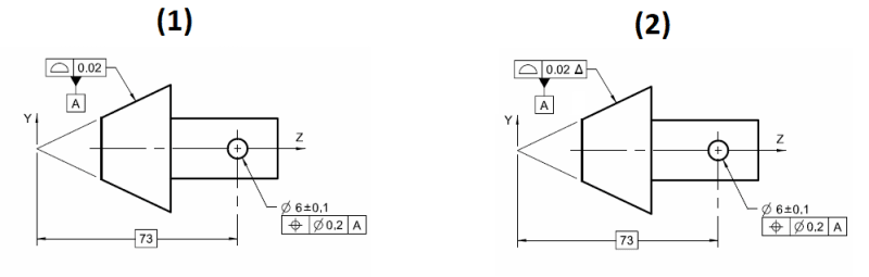
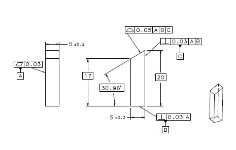
A designer applied perpendicularity feature control frame with the leader pointing to a centerline representing the center plane of an internal taper feature (a "pocket" with symmetrical non-parallel opposed surfaces). I don't consider this specification valid according to ASME Y14.5-2009 but I'm struggling to provide a good explanation of why perpendicularity shouldn't be used this way. The one use of perpendicularity I know when it is applied on a virtual, derived geometry (as opposed to an actual surface) is when a center plane/axis of a feature of size is controlled. It doesn't seem right in the context of a tapered feature, not associated with a size dimension - but I can't form a good argument why. A valid point is that a center plane can be derived from a tapered feature (for example, a datum plane derived from tapered datum feature), and I suppose that a way to evaluate the derived plane orientation relative to a DRF can be found. I need your help, please.
 
Replies continue below

Recommended for you

pylfrm said:
Perhaps the simulator surface diameters should be minimized while remaining equal. Perhaps the sum of the simulator surface diameters should be minimized. ASME Y14.5-2009 doesn't really provide a clear answer. The "Means this" portion of Fig. 4-25 just says "smallest pair of coaxial circumscribed cylinders".

I agree about the different possibilities. Since there seems to be no default perhaps each case should get a separate treatment. The "fitting routine" (per para. 4.17) should be specified in a note according to what represents the conditions at functional assembly best.

pylfrm said:
For the minimization, you would need a way to convert "the distances between its own surface and the actual surface of the feature" into a single value to be minimized. Perhaps you would minimize the maximum distance, the sum of the distances, or the sum of the squares of the distances. There are infinite possibilities here, but those three seem particularly worthy of consideration. I suppose it should also be specified that the distances are to be measured normal to the envelope surface.

I agree here too. I assume "the sum of the squares of the distances" is also the new default stabilization algorithm for datum feature simulators per the 2018 revision. This would be my pick.
 
Based on this I am not considering the author as someone that "tries mightily" to stuff cones into the box of IFOS; there is a high probability that he took part in creating that box, or at least is well aware of the intentions of the people who created it and has a pretty good idea of what fits in that box.

If we're talking about experts and committee members, I've already posted this on the other thread. As opposed to committee members with unknown influence on the decision making process - thoughts from Evan Janeshewski(axym) of Axymetrix Quality Engineering Inc. and Vice-Chair of the Y14.5.1 committee responsible for releasing the updated math standard Y14.5.1-20xx.

I hope Evan once again doesn't mind my mentioning him again. I don't mean this as an unequivocal endorsement "he said it and thus it is so" - I take his statements with the same healthy skepticism as any other expert and his position does not grant him special power to be inherently correct, though I think it does say something of his qualifications. It just so happens I take his with more weight as I have determined from many conversations (both directly and indirectly) his rationale is almost always very sound and strives for mathematical/geometric rigor, as opposed to the article you have linked - an expert has made an offhand comment "In the new standard, a hex, square, cone, or other similar type of features can used as a feature of size" without any direct support from the standard (again, other than a generous reading of IFOSb description) or any rationale as to why this is so. Even in the discussion I linked to above Evan strives for mathematical rigor - Norm's statement, nor do any of his statements regarding cones as a FOS, that "Can you pick up a cone with your opposing thumb and fore finger?" does not qualify as such for me, and are easily dismantled by consideration of the actual geometry at hand (ie: ignoring friction).

Again, after 60+ years of the Y14.5 standards without an explicit example of cones/tapered features contained in the Y14.5 or Y14.5.1 standards utilized or described as a FOS (at the very least a position/orientation tolerance applied) this is either a vocal minority which is unable to convince the committee majority that cones should be categorized as FOS or are unable to come up with a robust rationalization/description of how such features and their related envelopes should behave in the same context of other FOS. I don't see either case as being a very strong one for the "cones as a FOS" argument.

I think that a good reference for the required length of a theoretical simulator is the length of a tolerance zone.

I don't. First as you noted the height/length of the considered tolerance zone has a direct effect on the allowed variation, an infinite simulator does not. An infinite tolerance zone for example position/orientation tolerance zone which the axis of an RFS feature FOS must fall within would require perfect orientation to satisfy the tolerance. Not so for an infinite simulator.

Secondly the behavior you noted only happens with a tolerance zone where the axis/centerplane is considered (ie: RFS resolved geometry interpretation). When we instead consider the surface, for example the VC (and simulators for VC) for MMC/LMC can be infinite without impact on conformance. A datum feature simulator deals with the surface of the feature of interest. I don't see how the comparison is relevant.

A finite simulator for a conical feature can more easily be described as potentially being able to be "expanded" or "contracted" as these words are part of the AME definition,

A finite simulator "looks" more like its "expanding/contracting". The behavior you have described thus far is no different or easier to describe than if it were infinite.

Burunduk said:
A cylindrical theoretical feature has size because all circular elements along it have size - identical size. You say that a profile control for a conical feature doesn't control size. Does it mean that the circular elements along a cone don't have size, or does it mean that any circular element along the feature can be produced at any random size and still conform to the drawing specification? To clarify what I mean: can the conical feature from fig. 4-45 be produced with the theoretically smallest circular element at 50mm diameter as produced, the theoretically largest element at 80mm diameter as produced, and a 49.5mm diameter circular element somewhere in between, and be within the profile tolerance?

This would not be perfect form. Your example does not hold up to scrutiny anyway - a form control can control relative size of elements (ie: cylindricity), this does not make it a size control. A 50 +/-1 dia cylinder with 0.1 cylindricity tolerance cannot have simultaneously both a 50 and 49.5 circular element "randomly" inserted along its length. This does not mean the cylindricity tolerance controls size.

If you are saying that you define the ability of a form tolerance to control the relative size of surface elements as a size control, this is not supported by the standard. Take the 2018 dynamic profile tolerance modifier - this would be equivalent to cylindricity if applied to a cylindrical feature without datum references. See the section on dynamic profile modifier in Y14.5-2018:

Y14.5-2018 section 11.10 said:
A profile tolerance zone is static and controls both the form and size of the considered feature unless the dynamic profile tolerance modifier is applied. When it is desirable to refine the form but not the size of a considered feature that is controlled by a profile tolerance, the dynamic profile tolerance modifier, Δ, may be applied to a refining profile tolerance. The function of the dynamic profile is to allow form to be controlled independent of size.


Split the part from fig. 8-19 right in the middle of it. You will get 2 separate parts each with a portion of the original internal feature. The original pocket was a feature of size. Each of the split portions of it is not, and they represent my view on how a non-planar non-FOS looks like. I am pretty sure you get the idea, and if the terms I used fail to describe it properly, you probably can come up with a better definition of your own for this type of features.
If the entire shape including the flat is controlled with a single all around profile tolerance then indeed it is type (b). It doesn't have a defined axis but neither do other irregular features of size such as in fig. 8-19. A geometrical center can still be found.

Being able to describe precisely WHY a feature isn't a FOS is just as important (if not more so) as being able to describe why another feature is a FOS. It shows consistency in the criteria and in their application. I'm not really interested in a description of the features themselves, I'm interested in your reasoning on how certain features do or don't satisfy your criteria (or your interpretation of the standard's criteria) of what a FOS is. If these criteria can't be consistently applied in both cases, then either new criteria or a new interpretation should be sought out. WHY do you believe fig 8-19 split down the middle is not a FOS? If your reasoning is lack of a "geometrical center" - what is your criteria for finding such a geometrical center?

In the same vein - WHY are or are not the below FOS?

nonFOS_-_consistency_mtc8pq.png


the ultimate UAME envelope is the one that contacts the high points of the feature in a way that minimizes the distances between its own surface and the actual surface of the feature.

I think this could be defined more precisely.

The requirement that the envelope "contacts the high points of the feature" leads to the question of which points are high points. I think it would be simpler to replace this with a requirement that no points of the feature violate the envelope. Suitable contact would be ensured by the minimization.

For the minimization, you would need a way to convert "the distances between its own surface and the actual surface of the feature" into a single value to be minimized. Perhaps you would minimize the maximum distance, the sum of the distances, or the sum of the squares of the distances. There are infinite possibilities here, but those three seem particularly worthy of consideration. I suppose it should also be specified that the distances are to be measured normal to the envelope surface.

I have to assume (just based our prior conversations) your implication here is that such an envelope is valid only if specifically noted as such - through a note or similar. If so I agree - I sort of assumed that by your response on (15 Nov 19 04:05) that such a method would be contained in the specification/note you referenced. You're not implying this is the default behavior for the UAME of a conical feature per the standard*, correct?

As noted by Burunduk the constrained L2 (single solution) is the default stabilization procedure for datum feature simulation per Y14.5-2018 and Y14.5.1-20xx. I don't think theres any implication in the standard that this applies to the definition of a FOS or UAME (not that it can't be - only that its not implied by the standard)*. To me this would actually conflict with the requirement for the UAME to be of maximum/minimum size - I could easily envision a feature whose constrained L2 is not coincident with the envelope of maximum/minimum size. In fact, it seems to me that as a result for a FOS datum feature even during datum feature simulation the UAME maximum/minimum envelope would be the default, unless per Y14.5-2018 section 7.11.2 there are "irregularities on a datum feature are such that the part is unstable (i.e., it rocks)" (ie: due to variation/irregularities there is no minimum/maximum).

*Edit: I want to clarify that I mean the default UAME behavior for FOS per the standard. I could see an argument for applying the concept to FOS produced with variation which causes instability and as a result there would be no minimum/maximum. Where I see an issue is in applying this as the default condition to the nominal geometry as well.
 
I agree about the different possibilities. Since there seems to be no default perhaps each case should get a separate treatment. The "fitting routine" (per para. 4.17) should be specified in a note according to what represents the conditions at functional assembly best.

That's probably a good approach given the current state of affairs.

I think it would be better if the standard had a single definition for the UAME of any feature that has one, and for the behavior of any primary datum feature reference based on a UAME. It would also be good for that definition to be very simple. As usual, it would be possible to specify different datum feature reference behavior with a note if desired.


I agree here too. I assume "the sum of the squares of the distances" is also the new default stabilization algorithm for datum feature simulators per the 2018 revision. This would be my pick.

I don't believe ASME Y14.5-2018 specifies what exactly is to be minimized. See the 17 Sep 19 02:47 and 17 Sep 19 13:33 posts in thread1103-457989.

Would you say the following procedure will correctly determine your proposed UAME for the conical feature scenario?

Consider the infinite set of all candidate UAME axes that satisfy the position tolerance. For each of these axes, construct a ray (half-line) through each point on the actual feature surface such that the initial point of each ray is on the axis and the orientation of each ray relative to the axis matches the direction of taper and basic included angle specified for the feature. Find the ray with initial point farthest in the direction of decreasing cone diameter. Revolve this ray around the axis to create a conical envelope. Calculate the sum of the squares of the normal distances from this envelope to the points on the actual feature surface. The conical envelope that produces the smallest sum is the proposed UAME.


You're not implying this is the default behavior for the UAME of a conical feature, correct?

I'm only trying to arrive at a precise description of what Burunduk proposes to be the UAME.


pylfrm
 
chez311 said:
As opposed to committee members with unknown influence on the decision making process ...

I should mention the background of the author:

Al Neumann, President/Director of Technical Consultants Inc (TCI):
[li]A member on the ASME Y14.5, Dimensioning and Tolerancing subcommittee for the past 22 years.[/li]
[li]Currently serving as vice chair on the ASME Y14.5 subcommittee on dimensioning and tolerancing.[/li]
[li]A past chairman on the US Technical Activities Group to ISO on Dimensioning and Tolerancing and Mathematical Definitions.[/li]
[li]A senior member of the Society of Manufacturing Engineers and the American Society of Mechanical Engineers.[/li]
[li]A member on the ASME Y14.5.1 subcommittee on Mathematical Definitions of Dimensioning and Tolerancing.[/li]
[li]Past service on national and international standards committees for the past 25 years.[/li]

In the referenced thread, I don't understand statements like: "Does it have opposing elements? No, they're only partly opposed and never fully opposed so an actual local size is not defined". Doesn't a point on a conical surface face an opposing point on the same surface rotated 180° about the axis? I assume you understand the meaning of "partially opposes" so perhaps you could clarify. He didn't explain why the actual mating envelope for a cone isn't "rigorously defined".

chez311 said:
A finite simulator "looks" more like its "expanding/contracting". The behavior you have described thus far is no different or easier to describe than if it were infinite.

A finite conical simulator limited between two specific diameters can expand/contract maintaining a fixed included angle, unlike an infinite fully formed simulator. This is why they are different.

The bolded portion of your Y14.5-2018 citation says: "The function of the dynamic profile is to allow form to be controlled independent of size". This exactly why for many features - in my opinion cones included, form and size characteristics are linked together within a profile tolerance. In many cases this is the default condition, otherwise there would be no need in creating a new modifier to produce independence between the two.

chez311 said:
a form control can control relative size of elements (ie: cylindricity), this does not make it a size control. A 50 +/-1 dia cylinder with 0.1 cylindricity tolerance cannot have simultaneously both a 50 and 49.5 circular element "randomly" inserted along its length. This does not mean the cylindricity tolerance controls size.

Provide me the basic angle of a cone and the profile tolerance zone size and I'll be able to tell you the maximum and minimum diameters at any location from the apex of the true profile. An actual conical feature will have to be best fitted into that tolerance zone and as a result, the diameters (size) along it are limited. Provide me the cylindricity tolerance on a regular cylindrical feature of size and I won't be able to tell you anything about any diameter, because cylindricity is a pure form control and it is different.

chez311 said:
I'm not really interested in a description of the features themselves, I'm interested in your reasoning on how certain features do or don't satisfy your criteria (or your interpretation of the standard's criteria) of what a FOS is.

The criteria for what features can and can not be FOS should only be looked for in the definitions in the standard. My understanding is that basically all features that can be enclosed or enclose envelopes of form that is either a sphere, a cylinder, a pair of parallel planes or any other closed-form that repeats the theoretical form of the feature can be considered a feature of size.
As for the less-than-half-spheres and related features, I was pondering over them prior to your post and still do. A less-than-half-sphere doesn't have the opposed points needed to derive a center point but arguably one can treat it as a surface of revolution. The issue would be lack of an unambiguous location and orientation of a revolution axis - unlike with the cone there are infinite possibilities. For me, the existence of a defined axis indicates (but not a prerequisite to) the existence of an actual mating envelope. You show an axis perpendicular to a flat surface. To form an opinion on that it would help to know how the features are dimensioned and toleranced. If the flat surface and the partial spherical surface cannot be treated as a single irregular FOS, such direction is not defined for an unrelated AME axis. On the other hand, if they can be treated as a single feature (toleranced by profile all over) It is for sure an IFOS, regardless of an axis.

 
pylfrm,
The procedure you described sounds like the correct way to find the least squares envelope for a conical feature, which I believe is also the UAME envelope.

According to a source referred to by greenimi later in that thread, an algorithm for this should have been "further outlined in ASME Y14.5.1 Mathematical Definitions of Dimensioning and Tolerancing Principles to be released at the end of 2019".
 
I should mention the background of the author:

I'm sure Mr Neumann is a GDnT expert in his own right - I should not have discounted him in that respect. Having said that, it does not exempt him or anyone else from having to back up his statements with supporting logic in the form of direct support from the standard or the geometry/math. The article you posted is notably devoid of this. I really don't care for pitting one expert against another based solely on their qualifications - I don't think this is a worthwhile endeavor, I only presented a counterexample as I thought it should be shown that this is not a unanimously held opinion by well respected experts. I think its much more productive to consider the merits of the arguments themselves.

I have not seen a sufficient (nor even remotely mathematcially/geometrically rigorous) explanation by any expert as to why a cone should be considered a FOS. Most of the arguments I've seen boil down to being able to derive an axis - an axis is not a requirement for a FOS as I've shown several times over. An axis only implies symmetry.

A cone is a commonly encountered feature. There are several examples of cones in the Y14.5 standard, none of which are treated as FOS. We're on our second version of the standard which allows for IFOS. As I've said, all signs point to very weak support for cones as a FOS.

In the referenced thread, I don't understand statements like: "Does it have opposing elements? No, they're only partly opposed and never fully opposed so an actual local size is not defined". Doesn't a point on a conical surface face an opposing point on the same surface rotated 180° about the axis?

They don't have opposing elements, "opposing" in this sense meaning in a direction normal to the surface at any point.

A finite conical simulator limited between two specific diameters can expand/contract maintaining a fixed included angle, unlike an infinite fully formed simulator. This is why they are different.

The behavior is the same. Considering part (finite) or all (infinite) of a cone does not change that fact. It only changes the appearance.

The bolded portion of your Y14.5-2018 citation says: "The function of the dynamic profile is to allow form to be controlled independent of size". This exactly why for many features - in my opinion cones included, form and size characteristics are linked together within a profile tolerance. In many cases this is the default condition, otherwise there would be no need in creating a new modifier to produce independence between the two.

I never said that standard profile doesn't control both form and size for many types of features - such as a cylinder or width-shaped or even IFOSb like the pocket in Y14.5-2009 fig 8-19. I said for a cone considered by itself it doesn't.

If you believe that profile controls both size and form of a cone considered by itself and that the dynamic profile modifier would separate those two, could you tell me the difference between (1) and (2) below? I see none, but perhaps you do.

dynamic_profile_mod_cone_g9zjmh.png


The criteria for what features can and can not be FOS should only be looked for in the definitions in the standard. My understanding is that basically all features that can be enclosed or enclose envelopes of form that is either a sphere, a cylinder, a pair of parallel planes or any other closed-form that repeats the theoretical form of the feature can be considered a feature of size.

"enclosed or enclose envelope of form"
"closed-form"
"derive a center point" (from quote below)

Despite your statement that criteria should "only be looked for in the definitions in the standard" only the first one of these three are found (or roughly found - this is of course not the exact wording) in the standard and it is not defined, so we must interpret it. As best I can tell your interpretation for "enclosed or enclose" (or more properly "contain or be contained by") is "touching" - if you have an alternate or more precise definition I would be interested to hear it (I'm not sure how else to interpret your 20 Nov 19 17:29 "As long as it's set, it contains/being contained"). I don't see how this rules out any feature - including a planar one.

The following two are not included in the standard and yet you have mentioned them, and without precise definitions to boot.

Cones are not "closed-form" by any definition I know of. Perhaps you have an alternate one. Regardless, its not included in the standard and without an exact definition I don't see how its relevant.

You have yet to provide a method to derive this "geometrical center".

A less-than-half-sphere doesn't have the opposed points needed to derive a center point but arguably one can treat it as a surface of revolution. The issue would be lack of an unambiguous location and orientation of a revolution axis - unlike with the cone there are infinite possibilities. For me, the existence of a defined axis indicates (but not a prerequisite to) the existence of an actual mating envelope.

None of the shapes presented nor a cone have opposing points as I defined above. I've already showed a shape which would not have a defined axis yet you consider an IFOSb - namely a cone with a flat (G). I'm still not clear, do you believe the semi-spherical shapes (A) or (B) to be FOS? If so why?

Your argument, like most considering a cone as a FOS, revolves around the derivation of an axis - which is neither explicit nor implied in the definition for FOS, indeed I have already shown shapes which you consider a FOS without a defined axis. In that case you pivot to derivation of a "geometrical center" - another term not included in the standard's definition of a FOS and I have yet to see your definition for such derivation.

All this means the "WHY" I was searching for is still missing. I am still not clear on WHY you determine one shape is a FOS and another is not.

nonFOS_-_consistency2_p5tp1s.png


As a side note on a previous comment:
I don't see how diameters of circular elements on a planar feature can have any meaning.
Y14.5-2009 section 9.4.1 said:
Where applied to surfaces constructed at right angles to the datum axis, circular runout controls circular elements of a plane surface (wobble).
 
chez311 said:
Your argument, like most considering a cone as a FOS, revolves around the derivation of an axis

It does not. See my post from 8 Jan 20 19:43: "For me, the existence of a defined axis indicates (but not a prerequisite to) the existence of an actual mating envelope." In other words, not all features of size have axes, but if a feature has an axis there is a very strong case for it to be a FOS, because the feature needs to be "contained" by a simulator in order to derive it, and "containment" implies UAME.

chez311 said:
They don't have opposing elements, "opposing" in this sense meaning in a direction normal to the surface at any point.
"Opposing" is not defined in Y14.5, and neither there is a requirement for FOS to have any kind of opposing elements. For me, it is no more than a rule of thumb for recognizing a regular feature of size, or simply a feature of size prior to the 2009 edition of the standard.

chez311 said:
I never said that standard profile doesn't control both form and size for many types of features - such as a cylinder or width-shaped or even IFOSb like the pocket in Y14.5-2009 fig 8-19. I said for a cone considered by itself it doesn't.

The point was not that profile controls both form and size, although it does. The point was that profile controls size by controlling form for some features, including cones.

chez311 said:
If you believe that profile controls both size and form of a cone considered by itself and that the dynamic profile modifier would separate those two, could you tell me the difference between (1) and (2) below? I see none, but perhaps you do.

That conical feature could be defined by two basic diameters and a basic distance between them. Since the tolerance zone needs to be only as long as the actual feature, the unmodified profile could reject features produced oversized/undersized. By enforcing the tolerance zone to be between specific diameters and with a specific length, we are no longer able to use different sections of an infinite tolerance zone to always accept features produced with a conforming angle and form only. A modified dynamic tolerance zone would be able to contract/expand maintaining the length of the actual produced feature and the basic angle.

chez311 said:
Cones are not "closed-form" by any definition I know of. Perhaps you have an alternate one. Regardless, its not included in the standard and without an exact definition I don't see how its relevant.

If you think of the mathematical term "closed-form", this is not what I meant. The correct wording is "closed shape", I hope you don't mind the kindergarten level link. I guess it is anyway better than my attempts to describe this type of geometries, judging by the outcome so far. If the shapes depicted there were outlines / true profiles of physical features, internal or external, those would have defined UAME forms and should be considered IFOS type b.

chez311 said:
You have yet to provide a method to derive this "geometrical center".
In my recent posts, I talked about centroids, lines through centroids in the direction of extrusion, etc. I guess it is not that important though because as I stated axes and other types of theoretical center geometries are not part of the prerequisites to fitting in the FOS criteria.

chez311 said:
I'm still not clear, do you believe the semi-spherical shapes (A) or (B) to be FOS? If so why?

I am not sure either. Judging only by the IFOS type b definition - probably yes. Judging by common conventions and thumb rules about opposed elements etc, they are not.

Regarding the side note: I didn't say circular elements sampled on a flat surface can have no use. I said that diameters of such circular elements have no meaning:
"I don't see how diameters of circular elements on a planar feature can have any meaning."
 
Burunduk said:
"Opposing" is not defined in Y14.5, and neither there is a requirement for FOS to have any kind of opposing elements

A definition that I found for opposing is from Alex Krulikowski book (Fundamentals of Geometric Dimensioning and Tolerancing).
I realize that is not the standardized definition (found in an official standard), but for what is worth here it is:

"In the language of GD&T, two planar surfaces are completely OPPOSED if ALL rays normal from each planar surface intersects the other surface. Two surfaces are PARTIALLY OPPOSED if SOME of the rays projected normal from each planar surface intersect the other surface. Two surfaces are NON-OPPOSED if NONE of the rays projected from each surface intersect the other surface."

 
Kedu, thanks for the citation.
I believe there is one two kinds of regular features of size that don't have opposed elements according to this definition.
 
The procedure you described sounds like the correct way to find the least squares envelope for a conical feature, which I believe is also the UAME envelope.

The definition of UAME for an external feature is based on minimizing the size of the envelope, subject to the constraint that the envelope remains outside the material.

The procedure I described is based on minimizing the separation between the envelope and feature, subject to the constraint that the envelope geometry remains constant and the envelope remains outside the material. It seems that the thing to be minimized doesn't match the definition, and the constraint doesn't match the definition either. How do you reconcile these differences?


chez311 said:
If you believe that profile controls both size and form of a cone considered by itself and that the dynamic profile modifier would separate those two, could you tell me the difference between (1) and (2) below? I see none, but perhaps you do.

That conical feature could be defined by two basic diameters and a basic distance between them. Since the tolerance zone needs to be only as long as the actual feature, the unmodified profile could reject features produced oversized/undersized. By enforcing the tolerance zone to be between specific diameters and with a specific length, we are no longer able to use different sections of an infinite tolerance zone to always accept features produced with a conforming angle and form only. A modified dynamic tolerance zone would be able to contract/expand maintaining the length of the actual produced feature and the basic angle.

I agree with chez311 that there is no difference.

Imagine the basic diameters of the circular edges at the intersections between the conical surface and the flat surfaces are 50 mm and 100 mm, and the basic width across those flat surfaces is 25 mm. Now imagine a part produced such that the actual dimensions are 60 mm, 110 mm, and 25 mm respectively. Are you saying that the non-dynamic profile tolerance would reject this part? Even if the flat surfaces had profile tolerances of 10 mm?


pylfrm
 
pylfrm said:
The procedure I described is based on minimizing the separation between the envelope and feature
... which for regular external features of size always equivalent to minimizing the size of the envelope, and for irregular features of size equivalent to scaling down the envelope. For different actual conical features with the same basic included angle, you should use different sections of the "axis-revolved ray" theoretical surface as the envelope according to the different ranges of diameters. This is equivalent to using a single section and scaling it (changing the diameters of all circular elements along it).

pylfrm said:
Imagine the basic diameters of the circular edges at the intersections between the conical surface and the flat surfaces are 50 mm and 100 mm, and the basic width across those flat surfaces is 25 mm. Now imagine a part produced such that the actual dimensions are 60 mm, 110 mm, and 25 mm respectively. Are you saying that the non-dynamic profile tolerance would reject this part? Even if the flat surfaces had profile tolerances of 10 mm?

I assume you claim that the feature will conform to a tolerance zone that extends beyond the the basic length between the basic diameters.
If the basic diameters of the true profile are outside the portion of the tolerance zone that covers the actual feature, that portion of the tolerance zone is not the intended portion, and the feature does not conform to the tolerance.

Think of a tab with an inclined top face controlled by profile and defined with 2 basic linear dimensions and a basic angle realtive to a horizontal bottom face referenced as a datum feature in the profile FCF. What controls the height (location) of the inclined top face relative to the bottom face? What is the meaning of the two linear height dimensions?
 
Kedu,

Thanks for the reference. I would say thats along the lines I would interpret the meaning of "opposed". It might need slight adjustment to consider interrupted features and IFOSa such as Y14.5-2009 fig 4-33 datum feature A but the general gist is there. Something like the following might be a more precise definition, which while perhaps not specifically mandated by the standard in all cases in all FOS definitions (though "opposed" parallel elements/surfaces does show up under RFOS), can be a good, generally applicable, and consistent rule of thumb/criteria:

Directly opposed - two points on a surface (or collection of surfaces) which have vectors normal to the surface which are coincident/colinear.

Indirectly opposed - two points on a surface (or collection of surfaces) which have vectors normal to the surface which are parallel and lie on the same plane (ie: non-skew).

Partially opposed - two points on a surface (or collection of surfaces), one of which has a normal vector which intersects the other point, whose corresponding normal vector is not coincident/colinear.

Partially indirectly opposed - two points on a surface (or collection of surface) which have lines normal to the surface which are not coincident/colinear which intersect at a third discrete point.

Non-opposed - two points on a surface (or collection of surfaces) which do not satisfy the above definitions.

Note the vectors mentioned above must both be on the same side of the surface/material (ie: either both outside or both inside the material) and pointing in opposite directions (towards/away from each other - coincident/colinear vectors would have one that is the negative of the other ie: multiplied by the scalar -1), to satisfy the directly/indirectly opposed criteria. For partially or partially indirectly opposed "opposite" is not as simple - I have not come up with a easy/succinct way to determine this, but they would still be required to be on the same side of the material. In the end I'm not sure it matters much as a FOS will not be comprised of only partially or partially indirectly opposed points.

One or more pairs of directly opposed points guarantees a FOS. A feature having no directly opposed points will require two or more pairs of indirectly opposed points to be a FOS, but this alone does not guarantee a FOS as it depends on the configuration - a more precise requirement might be able to be found with some effort, perhaps I'll circle back to this. A feature with only partially or partially indirectly or non-opposed points will not be a FOS.

Burunduk,

Which RFOS do you imagine doesn't contain directly opposed points?
 
"circular element, and a set of two opposed parallel elements".
Circular elements only have opposed points if they are part of a cylindrical surface. If the circular element is part of a conical feature or on the curved portion of a feature such as in fig. 8-26 in ASME Y14.5-2009, the normals to the surface coincident with the circular elements will not conform to the opposed criteria.
Despite of the word "opposed", the "two opposed parallel elements" will only be opposed by the mentioned definition if they are on two parallel surfaces, and I'm not sure that this is the intent of the standard. The parallel line elements used as a feature of size could be on a flat taper.
 
It does not. See my post from 8 Jan 20 19:43: "For me, the existence of a defined axis indicates (but not a prerequisite to) the existence of an actual mating envelope." In other words, not all features of size have axes, but if a feature has an axis there is a very strong case for it to be a FOS, because the feature needs to be "contained" by a simulator in order to derive it, and "containment" implies UAME.

I don't see the involvement of an axis/centerplane as a robust determination of a FOS. A feature could have one possible axis/centerplane, infinite, or none it really provides no real basis to determine if a feature is a FOS. Imagine a single less than half cylinder - one can derive a defined axis but is not a FOS. Conversely I've shown several times features which don't have a defined axis/centerplane but which are clearly FOS. I don't see how "a very strong case" is very useful at all here.

You keep mentioning "contaiment". You have yet to provide a working definition that implies anything more than contact or simply "touching", which as I said I don't see how that excludes any shape/feature including a single planar feature.

That conical feature could be defined by two basic diameters and a basic distance between them. Since the tolerance zone needs to be only as long as the actual feature, the unmodified profile could reject features produced oversized/undersized.
I assume you claim that the feature will conform to a tolerance zone that extends beyond the the basic length between the basic diameters.
If the basic diameters of the true profile are outside the portion of the tolerance zone that covers the actual feature, that portion of the tolerance zone is not the intended portion, and the feature does not conform to the tolerance.

Changing the way the basic geometry is defined does not change the tolerance zone. Pylfrm beat me to the punch, but I developed a figure previously so I will share it below. I see no difference between (1) and (2) below - the result is the same as if it had been defined with a basic angle. If you see a difference, could you describe a part which (1) accepts and (2) rejects or vice versa?

CONE_BASIC_GEOMETRY_2_yyxg3q.png


If you think of the mathematical term "closed-form", this is not what I meant. The correct wording is "closed shape", I hope you don't mind the kindergarten level link. I guess it is anyway better than my attempts to describe this type of geometries, judging by the outcome so far. If the shapes depicted there were outlines / true profiles of physical features, internal or external, those would have defined UAME forms and should be considered IFOS type b.

I was referring to 3D space, I see you are referring to "closed" 2D shapes extracted from 3D surfaces. I'm still ambivalent about how this is useful for determination of a UAME as well as how it can be more generally applied. A few issues:

- In features lacking a defined axis it is not obvious which cutting plane should be utilized to produce these 2D shapes.
- Features which are obviously FOS may not be made up of "closed" 2D shapes, say Y14.5-2009 fig 4-29 datum feature A which consists of a semi-circular profile or even just a simple width shaped feature consisting of two parallel planes.
- Features which you have already said you don't believe to be FOS like the one on the right from your (23 Dec 19 18:01) post. Lacking a defined axis and from my first point any defined way to determine which cutting planes should be utilized, certain cutting planes will produce "closed" 2D shapes.

Notably in this last case and others (I would say cones and similar shapes as well but we obviously disagree there), 2D shapes/elements themselves may be FOS but that does not tell us that the surface from which they are extracted qualifies as a FOS.

In my recent posts, I talked about centroids, lines through centroids in the direction of extrusion, etc. I guess it is not that important though because as I stated axes and other types of theoretical center geometries are not part of the prerequisites to fitting in the FOS criteria.

So are you implying that I should replace your statement "as long as a geometrical center can be found" with "centroid" instead of "geometrical center" ? Can you provide an example of a shape for which a centroid cannot be found?

If you don't believe that either the concepts of "2D closed shapes/elements" or "centroids/geometrical center" are applicable to determination of a FOS/UAME I would agree - and go even further to say that they are not useful "rules of thumb" as they cannot be generally applied to say whether a feature is a FOS or not, or if they can be I have not seen presented such a consistent way to do so. See my previous post on opposed points for what is in my opinion a more generally applicable and unambiguous rule of thumb.

What we are left with is still, as I mentioned further up in this post, your statement about "containment". Clarity as to what you mean here would be helpful.

I am not sure either. Judging only by the IFOS type b definition - probably yes.

If you believe (A) and (B) are IFOSb then (1) I think you'll find yourself even more alone in that viewpoint than on cones and (2) I am tending towards the fact that your interpretation allows almost any shape imaginable to be an IFOSb. I know you have stated several shapes which you do not believe are FOS - but without a more consistent and precise interpretation than whats been provided thus far I don't see how you reconcile those with (A) and (B) semi-spherical shapes (really I would say in addition to (G) too).
 
"circular element, and a set of two opposed parallel elements".
Circular elements only have opposed points if they are part of a cylindrical surface. If the circular element is part of a conical feature or on the curved portion of a feature such as in fig. 8-26 in ASME Y14.5-2009, the normals to the surface coincident with the circular elements will not conform to the opposed criteria.
Despite of the word "opposed", the "two opposed parallel elements" will only be opposed by the mentioned definition if they are on two parallel surfaces, and I'm not sure that this is the intent of the standard. The parallel line elements used as a feature of size could be on a flat taper.

You are conflating two different things - the 3D surface and the 2D elements extracted from it.

Take a cone for example.

2D circular elements extracted by intersection of the cone with a cutting plane - in the 2D space all points on the circular element have directly opposed points with normal vectors on said cutting plane. The circular element is a FOS.

3D cone - in the 3D space no points on the cone have directly or indirectly opposed points with normal vectors in 3D space. The 3D surface of the cone is not a FOS, despite containing 2D elements which are FOS.
 
pylfrm said:
The procedure I described is based on minimizing the separation between the envelope and feature
... which for regular external features of size always equivalent to minimizing the size of the envelope, and for irregular features of size equivalent to scaling down the envelope.

Assuming we're still talking about minimizing the sum (theoretically the surface integral) of the squared separations, that is not true for a nominally cylindrical or nominally square hole. I'm pretty sure it's just generally not true.

For a counterexample, imagine a nominally cylindrical hole that's actually produced more like a short slot with two flat sides connected by tangent cylindrical ends. If the flat sides are slightly non-parallel, one of the ends will have a slightly larger radius and will end up coincident with the maximum inscribed cylinder UAME. On the other hand, the least-squares cylinder will be smaller, contacting the flat surfaces roughly in the middle and equalizing the separation with the two ends.


For different actual conical features with the same basic included angle, you should use different sections of the "axis-revolved ray" theoretical surface as the envelope according to the different ranges of diameters.

Why shouldn't I use the entire thing? When would I care about anything other than the five parameters needed to describe the location of the apex and the orientation of the axis?


I assume you claim that the feature will conform to a tolerance zone that extends beyond the the basic length between the basic diameters.

Correct. In general, I claim that the tolerance zone covers the full extent of the actual produced feature.

Consider a related example where the drawing specifies a short piece of tube with inside diameter 50 mm BASIC, outside diameter 100 mm BASIC, and length 25 mm BASIC. A profile tolerance of 0.02 mm without datum feature references is applied to one of the flat end faces. Now imagine a part produced such that the actual dimensions are 60 mm, 110 mm, and 25 mm respectively. Cylindricity, concentricity, flatness, perpendicularity, etc. are all perfect. Would the profile tolerance reject this part? What if a flatness tolerance had been specified instead of profile?


If the basic diameters of the true profile are outside the portion of the tolerance zone that covers the actual feature, that portion of the tolerance zone is not the intended portion, and the feature does not conform to the tolerance.

How would you suggest the requirement be expressed if my interpretation is the intended meaning? I should clarify that the 10 mm profile tolerances mentioned in my previous post were intended to become part of a simultaneous requirement with the 0.02 mm profile tolerance.


Think of a tab with an inclined top face controlled by profile and defined with 2 basic linear dimensions and a basic angle realtive to a horizontal bottom face referenced as a datum feature in the profile FCF. What controls the height (location) of the inclined top face relative to the bottom face?

Nothing that you've described. The profile tolerance would be equivalent to an angularity tolerance except for the simultaneous requirement rules.

Two nonparallel planes don't have a location relationship. Three nonparallel planes have a location relationship if they are all perpendicular to a fourth though. If you want to control something beyond angularity of the inclined surface, involving a third surface as a secondary datum feature reference or controlled as part of a simultaneous requirement might achieve your goal.


What is the meaning of the two linear height dimensions?

As always, the meaning is that they define some aspect of the part's basic geometry. Whether that aspect is relevant or not depends on what tolerances are applied.


pylfrm
 
chez312 said:
Imagine a single less than half cylinder - one can derive a defined axis but is not a FOS

Actually what I mostly encounter is that it is considered problematic to derive an axis from an incomplete cylindrical feature which is "less than half": "180° rule", "opposed points", etc. I thought this was one of the main distinguishments between FOS and non-FOS. Where you can't derive an axis for an otherwise regular FOS, you can't apply exclusively FOS-related controls such as position RFS.

chez311 said:
You keep mentioning "contaiment". You have yet to provide a working definition that implies anything more than contact or simply "touching", which as I said I don't see how that excludes any shape/feature including a single planar feature.

It looks like the mathematical definition (Y14.5.1M-1994) doesn't go much further than "contact or simply touching" either:

"1.4.13 Envelope, actual mating. A surface, or pair of parallel surfaces, of perfect form, which correspond to an actual part feature of size, as follows:
(a) For an External Feature. A similar perfect feature counterpart of smallest size which can be circumscribed about the feature so that it just contacts the surface.
(b) For an Internal Feature. A similar perfect feature counterpart of largest size which can be inscribed within the feature so that it just contacts the surface"


I can see how the main pivot point for you would probably be "largest size" (for internal features) and "smallest size" (for external surface), but what defines how this size should be determined for envelopes of irregular features of size (consider for example the pocket from fig. 8-19)?

chez311 said:
Changing the way the basic geometry is defined does not change the tolerance zone ... If you see a difference, could you describe a part which (1) accepts and (2) rejects or vice versa?
I generally agree that changing the way the basic geometry is defined does not change the tolerance zone and I understand why you would probably say that both (1) and (2) could accept a feature produced with 37.5mm length and a range of diameters from 51mm to 81mm. What if the profile was applied all over?

chez311 said:
2D circular elements extracted by intersection of the cone with a cutting plane - in the 2D space all points on the circular element have directly opposed points with normal vectors on said cutting plane. The circular element is a FOS.
The definition brought by Kedu involved normals to the surface, nothing about 2D cutting planes. The surface is in 3D space. How can 2D elements isolated from the 3D space have opposed points?
 
pylfrm said:
Two nonparallel planes don't have a location relationship. Three nonparallel planes have a location relationship if they are all perpendicular to a fourth though. If you want to control something beyond angularity of the inclined surface, involving a third surface as a secondary datum feature reference or controlled as part of a simultaneous requirement might achieve your goal.

I think I understand how a simultaneous requirement might help (considering the different tolerance zones as part of a single structure tied with the basic dimensions) but I don't see how additional datum features make difference in the context of what I described. See the image below. Full DOF-constraining 3 planes DRF is defined. Also there are three nonparallel planes that as you say should have a location relationship since they are all perpendicular to a fourth. Would this prevent accepting a part produced with distances of 19 and 22 where the basic 17 and 20 are given? If yes, how?
INCLINED_TOP_FACE_beav2o.jpg


Edit: After giving it some more thought - would you say that the feature produced with 19 and 22 heights will be rejected because the height of the intersection lines between the considered feature's tolerance zone boundaries and datum plane C is defined? Similarly to how the intersection with datum axis A is defined in fig. 8-13?
 
After giving it some more thought - would you say that the feature produced with 19 and 22 heights will be rejected because the height of the intersection lines between the considered feature's tolerance zone boundaries and datum plane C is defined? Similarly to how the intersection with datum axis A is defined in fig. 8-13?

Yes.

My previous post was based on the assumption that the horizontal bottom face (now identified as datum feature B) is the only datum feature reference of the profile tolerance. I probably should have stated that assumption more clearly.


pylfrm
 
Status
Not open for further replies.

Part and Inventory Search

Sponsor