Eng-Tips is the largest engineering community on the Internet

Intelligent Work Forums for Engineering Professionals

Orientation of diagonal stiffeners 1

Status
Not open for further replies.

tmalik3156

Structural
Jun 21, 2021
92
0
6
CA
Good day all.

May be this is a simple question, but we learn by asking those who know.

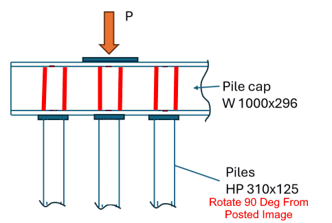
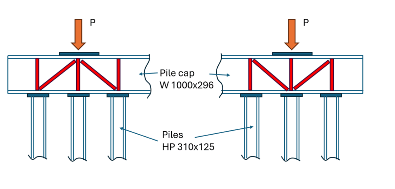
We are designing a steel foundation for a Bailey type bridge system. This will be a permanent bridge. The foundation consists of three piles (HP 310x 125) at each end of a pile cap (W 1000x295). The Pile cap carries load (P) of the bridge. We need stiffeners to prevent buckling of the web and distortion of the flanges of W 1000x295. Question is, what should be the orientation of the diagonal stiffeners (shown in red)? Is it like the one shown on the left, or the one on the right?
Thank you

Foundation2_sgqtd1.png
 
Replies continue below

Recommended for you

Either one will work. It just depends on whether you want to use larger diagonals to prevent compression buckling (for the configuration on the left), or design the connections at the ends of the diagonals for tension and fatigue.

I think most designers would rather upsize the member to handle the compression than deal with the possible fatigue issues. That's what I would do, so I would use the configuration on the left. That one also may have the advantage of allowing you to decrease the size of the exterior vertical stiffeners, or eliminate them altogether.

Depending on the length of the pile cap, it may be more economical to use a heavier cap beam, maybe even a plate girder, that doesn't need stiffeners. Steel is cheap; fabricating stiffeners, gusset plate and connections is expensive.
 
@BridgeSmith
Thank you very much for your reply.
We are concerned about misalignment due to pile or cap installation error (it's a remote location). There might be eccentricity in load P both in longitudinal and transverse directions. We wanted to prevent distortion of both the flange and the web due to eccentric loading. Moreover, we wanted to make sure that load P gets transferred to all three piles, as one single pile wouldn't generate enough skin friction. These are the reasons for considering the stiffeners in design. Indeed, avoiding them would be cost-saving.
 
tmalik31566 said:
1) ...concerned about misalignment due to pile or cap installation error. There might be eccentricity in load P both in longitudinal and transverse directions.

2) ...load P gets transferred to all three piles, as one single pile wouldn't generate enough skin friction.

1) Typical tolerance for pile driving is (horizontally) within 75mm of planned location, for each pile. Getting six pile is a (precise) straight line is going to be challenge (even if the pile driver knows what he is doing... using a template).

IMHO, longitudinal pile misalignment is not a big deal... I would consider double web stiffeners at each pile location (shown below).

Transverse pile misalignment is a problem. A partial solution is to rotate the HP 90[sup]o[/sup] from the posted image so that The HP's major axis is resisting transverse eccentricity. (The posted image has the minor HP axis resisting transverse eccentricity.) Another step is to have (and enforce) a "tight" pile driving spec to minimize the problem.

2) Has a geotechnical engineer been consulted? A group of friction piles typically distribute load among themselves automatically... unless deflection is too large. A W1000 supported by closely spaced HP and loaded directly above each pile group will have trivial deflection.

If the piles are true point bearing, your concerns could be valid... but they are not point bearing piles.

Bridge_On_HP-500_ynyxuo.png
 
Thank you SlideRuleEra for your detailed reply.
I made a mistake in my original sketch. The strong axis should be oriented parallel to the cap, as you indicated.
We have the Geotechnical Report, and the skin friction values are known. We are not relying on end bearing.
We expect the pile cap to behave like a rigid body without significant deflection, and so the three piles are expected to carry equal (P/3) loads, unless there is really bad misalignment.
Thank you for the idea of double stiffeners. We will think about it.
What did you mean by a "tight" pile driving spec?
 
tmalik3156 - A "tight" pile driving spec would be written for the requirements for this project, not just a "standard" spec that would be used on a typical pile driving job. For example, a "tight" spec could require the following:

1) Pile driving Contractor must provide proof of his experience. (One Reason, of Many: Keep unqualified Contractors away.)

2) In advance of starting work, Contractor must provide a plan for driving this project's piles for acceptance by the Engineer. (One Reason: To force the Contractor to think thru this project's requirements.)

3) Set tolerances that may differ from "routine" work. Say, location of head of driven pile to to be accurate within 50mm, transverse and 75mm,longitudinal. (One Reason: To inform the Contractor that transverse tolerance is more important than longitudinal tolerance.)
Remember, the head of the pile is probably in mid-air, not at ground level. Meeting any mid-air tolerance is difficult, even for an experienced pile driver... but it can be done.

4) Require the Contractor to perform ALL pile driving ONLY when a qualified, third-party pile driving inspector is onsite. (One Reason: Make it clear to the Contractor that no short-cuts will be permitted.)

5) The third-party inspector has authority to enforce the Contractor's accepted plan. (One Reason: Again, no short-cuts.)

6) Engineer to keep an open mind about the final result. If "something" is out of spec, but is not a problem, waive that spec requirement.

These are just some examples of my idea of a "tight" (but reasonable) pile driving spec. Note that for the most part, the Engineer is NOT telling the Contractor what to do or how to do it. The goal is to get a qualified Contractor to make his own plan, then make sure that the Contractor does exactly what he said he would do in his own plan.

Concerning double stiffeners: Be sure to space them far enough apart to allow fabrication welding between the stiffeners. The spacing is not that important. The load is analyzed as a point load, but by the time load passes thru the bearing plate (thick, with length appropriate for plate thickness), what the beam is subjected to is load distributed over the length of the bearing plate. The distributed load may not be uniform, but it WILL be distributed.


Status
Not open for further replies.
Back
Top